Build a Counter-Pressure Bottle Filler: Projects
For most homebrewers who brew long enough, kegging eventually becomes part of their process. The primary advantage of kegging is that only one packaging vessel needs to be cleaned and sanitized as opposed to dozens. However, in addition to that, there is a certain convenience factor. Kegs are perfect for the moderate term storage needs of the homebrewer, as well as home bar dispensing and picnic applications. Still, there are some occasions — such as contests or homebrew club meetings — for which we might wish to have bottled homebrew. The counter-pressure filler is a device which allows brewers to transfer conditioned beer from a keg to a bottle. This transfer occurs under pressure, which minimizes the loss of carbonation that would occur by simply running beer from a tap into a bottle or growler.
My counter-pressure filler was assembled with parts costing a total of $28 obtained from a neighborhood plumbing supply store and assembled in less than an hour.
Parts list:
1/4” bronze tees (2)
1/4” brass ball valves (2)
1/4” OD copper x 1/8” MIP angle needle valve (1)
1/4” brass nipples (2)
1/4” X 1/8” brass bushing (1)
1/4” threaded – 1/4” compression fitting (2)
1/4” threaded – 3/8” compression fitting (1)
1/4” copper tubing (16 inches)
3/8” copper tubing (6 inches)
1/4” barbed fittings (2)
Rubber stopper (1) sized to fit bottle or growler
Tools list:
Wrenches/pliers
Tubing cutter
Drill with 1/4” bit
Teflon tape
Total cost as shown: $28 (US)
The long central tube delivers CO2 to the receiving bottle. This purges the air from the bottle and allows for its pressurization. It also delivers the carbonated beer. This is accomplished by opening and closing the valves in the proper sequence, and by using a venting assembly, which is a sort of sleeve that fits over the central tube and is fitted with a stopper that seals the bottle so it retains the 4-6 PSI of pressure used during bottling.
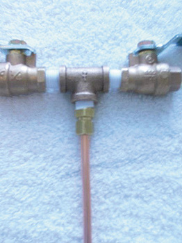
Assembly begins with the upper part of the unit. All threads are coated with teflon tape. The two ball valves are connected to the sides of one of the tees using the brass nipples. (See photo 1.)

1. The ball valves, which control the flow of carbon dioxide and beer into the unit, are connected to a tee.
The 1/4” threaded to 1/4” compression fitting is connected to the bottom of the tee and the length of 1/4” copper tubing is connected to that. (This is shown in photo 2.)
The venting sleeve is constructed by attaching the 1/4” threaded to 3/8” compression fitting to one side of the remaining tee. The 3/8” tubing is connected to that and cut. It doesn’t need to be any longer than a couple of inches. Tape the threads of the bushing and insert it in the center of the tee. Again, treat the threads of the needle valve and screw it into the bushing (as is shown in photo 3. Photo 4 shows the assembly before the needle valve is attached to the tee.)

3. The venting sleeve and needle valve are attached to their tee.

4. The needle valve prior to attachment to the tee (note the bushing).
The remaining 1/4” threaded to 1/4” compression fitting attaches to the other end of the tee. Before doing so however it must be reamed out. This fitting is designed to affix to the end of a length of tubing and there is a small lip of material inside the fitting that butts up against the end of that tubing. This lip must be removed using the drill to allow the fitting to “float” over the 1/4” tubing.
Once assembled, the venting sleeve slips over the 1/4” tubing of the main body and is secured with the 1/4” threaded to 1/4” compression fitting.
The 1/4” tubing extends out and through the 3/8” tubing and is cut to the appropriate length to reach within an inch (2.5 cm) of the bottom of the bottle being filled. The stopper is placed on the 3/8” tubing, moved as far up (toward the compression fitting) as it will go, and cut to a length just below the bottom of the stopper. If it’s too long, it will suck beer out of the bottle during venting.
Add 1/4” barbed fittings for the “beer in” and “gas in” lines, tighten all fittings, and assembly is complete.
Theory and use of the filler is described in detail in the November 2002 issue of BYO, but the basic process is as follows:
Once the unit is sanitized, close all of the valves. Connect poly tubing lines to the barbed fittings on the filler from your CO2 bottle and keg of conditioned beer. Place the filler on the clean bottle with the stopper snugly in the neck. Open the needle (bleeder) valve, then open the “gas in” valve. Allow CO2 to flow into the bottle and out the bleeder for a few seconds to purge the air from the bottle. Close the bleeder valve and allow the bottle to equilibrate to dispensing pressure (4-6 PSI). Close the “gas in” valve. Open the “beer in” valve. If everything was done correctly up to this point, nothing will happen.

Slowly open the bleeder valve. The idea is to release just enough pressure from the bottle to allow the pressure in the keg to move beer into it, but not enough to allow a sudden degassing of the beer. Control the pressure release carefully by opening the valve only as much as necessary and by closing it periodically as required. When the bottle is filled, close the valves, gently break the seal of the stopper, remove the filler, and cap the bottle.
It takes some practice to coordinate the steps and keep the pressures in all of the vessels where it needs to be to facilitate the process, and even with such practice there will still be a little carbonation loss. It will be far less however than it would be if the filler had not been used. Ensuring that the beer (and the bottles) are well chilled will help as well. This unit is designed as an economical alternative to the common (but more pricey) stainless steel versions. Although stainless is preferable, this is adequate for infrequent use and, in the author’s tests, didn’t contribute to any significant degradation of beer quality during short exposure times.