Pumped Up Toolbox: Projects
There are many reasons why a pump can be a significant time saving addition to your brew day. How the brewer implements the equipment to the process can have just as large an impact. About three years ago, I decided the time had come to upgrade to a pump, but without a dedicated brewing structure, I needed to design a portable solution. Since there was also an ongoing need to organize many of the smaller brewday items, this design for a brewing toolbox seemed to solve multiple needs at once.
In this configuration, the brewer has control over the transfer of wort during mash/boil recirculation and for vessel transfer. In the past I have used my pump in conjunction with a plate chiller with great results and I currently use it with a counterflow chiller and recirculation.
When I first developed this piece of equipment I had doubts about the pump heat displacement and the durability of the build. This configuration has been used for dozens of brew sessions, usually with the lid closed in both the heat of summer and ice of winter. I have run the pump nonstop for up to 45 minutes during a large lager batch chilling recirculation (I typically begin recirculation with 15 minutes remaining in the boil to sanitize the pump, lines and chiller). Over time, there has been no visible or noticeable impact to the pump performance — and more importantly to the quality of the beer.
My system uses a hodgepodge of brass and stainless fittings. Brewers should be sure to properly pickle, or remove surface lead, from brass fittings prior to use on brew day. With the exception of the March pump, all the components of this build can be found at any local home improvement store, although stainless fittings may have to be sourced online.
Once you acquire a pump, take a trip to your local home improvement store and look for a plastic toolbox that has adequate storage options and space for the pump motor height, plus about 2 inches (~5 cm). It is better to be conservative and go bigger if you have any doubt. Once all of the required items are sourced, it is time to get to work.
First thing is first: if you do not have access to a GFCI (ground fault circuit interruptor) outlet during your brew day, you must modify this plan to incorporate an inline GFCI breaker, otherwise do not take on this project. You can find an inline GFCI breaker at most homebrew stores. Liquid and electricity can seriously hurt or kill you.
Parts List:
Optional Parts
March 809 Pump
Misc Fittings
Plastic Toolbox
Inline GFCI Breaker
Grounded Extension Cord
Switch Box Required Tools and parts
Electric Switch
1” Hole Saw
(2) Coat Hook
Drill
Scrap 2×4
Screw Drivers (Phillips and Slotted)
6” Worm Clamp
Utility Knife
1⁄2” Street Elbow Fitting
(2) Wire Clamps
Wire Nuts
Wire Stripper
(8) Size 10 Machine Screws
Marker
(8) Size 10 Machine Nuts
Step 1 – Remove the four screws securing the pump head to the pump motor, and remove the pump head.
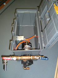
Step 2 – Affix the pump motor to the 2×4 scrap using the worm clamp. Ensure the wire box on the pump motor is accessible for later use (see Photo 1, below).

Step 3 – Dry fit the pump and 2×4 inside the toolbox, and mark where the pump shaft meets the toolbox wall, mark this point with a marker. Using a drill, make a pilot hole at the point you marked inside the box.
Next, using a hole saw centered on your pilot hole, drill through the toolbox wall. The hole should be large enough for the shaft to easily fit through the wall. Remove any burrs with a knife. Your pump should now easily fit inside the toolbox and the shaft should fit through the wall (see Photos 1, above, and 2, below).
Step 4 – Cut a 1” (2.5 cm) hole in the middle center of the back of the toolbox for the power supply cord (see Photo 3, below).

Step 5 – Cut the female end off the extension cord. Cut a 12–15 inch (~30–38 cm) section of cord, and set aside. Feed the cut end of the longer cord through a wire clamp and the hole drilled in step 4. Remove the insulation and strip the three wires (green, white and black) from the longer section of cord. Tighten the wire clamp with about 12–15 inches (~30–38 cm) of spare wire inside the toolbox (see Photo 2).
Step 6 – Strip the insulation from both ends of the shorter cord, and strip the insulation from the three interior wires at both ends. Remove the cover plate from the pump motor to expose the pump wiring. Match the colors to one end of the small section of extension cord and secure with wire nuts. Re-attach the wiring cover plate (see Photos 2 and 4, below).

Step 7 – Measure the outside dimensions of your light box and mark the dimensions on the front of the toolbox. Cut out the marked dimensions with a knife. The switch box should dry fit into the new hole. Punch out one wire hole in the switch box and feed in the remaining end of the shorter cord and the remaining end of the longer section (leave a minimum of 5 inches/13 cm of cord inside of switch box, excess can always be trimmed later). Secure both cords with a wire clamp. Secure the switch box to the toolbox with screws and nuts as shown (see Photo 4, above).
Step 8 – Mark the non-stripped section of cord (this is your source wire). Strip the insulation and interior wires from the longer section of cord. Feed both the shorter and longer cords through the wire clamp and the back of the switch box. Wire the switch using the two black exposed wires. Ensure the ground (green) and current (white) wires are secured with wire nuts, and attach the switch to the switch box. Attach the switch plate. Tighten the wire clamp (see Photo 4, above).
Step 9 – Dry fit the pump head to the outside of the toolbox on pump motor shaft with the inlet at the 6 o’clock position and the outlet at the 12 o’clock position. Using a marker, mark the location of the six pump head screws and remove the head and move the motor so the drill does not cause it damage. Using a 1⁄8” bit, drill pilot holes for the four marked screw holes. Refit the motor and head and secure the head to the motor using the manufacturer’s screws. The pump should be secure to the toolbox now. Add the street elbow fitting to the inlet port of the pump head. The street elbow will allow for easy tubing connection later.
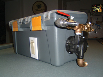
Step 10 – Screw the two coat hooks to the back of the toolbox as shown in Photo 3. Wrap the exterior cord around the hooks as shown in Photo 5, (below).

Step 11 – Fill the toolbox with your brewing items. At the risk of sounding obvious, you should think about where you place your items. The pieces you may need in a pinch or have easy access to should be either in lid compartments, or the inner tray so you do not have to rummage (see Photo 6, below).

Pump priming and additional fittings
One of the largest issues with first time pump users is priming the pump. Without proper priming the pump will not create a vacuum and not perform properly. Because of the inlet/outlet orientation, the vacuum can be created fairly effortlessly. When using the pump, position the toolbox lower than the vessel, open the valve on your vessel and allow the liquid to flow into the pump head. This will force the air out of the pump head. After a minute or two, switch on the pump and you should be flowing issue free.
In my setup, I have a tee fitting on the outlet of the pump head, with two valves. I use one valve (red) to throttle the pump flow rate. Flow must be controlled after the pump, never before. I use the blue valve to purge any air in the pump to create my prime or to collect wort samples for either gravity readings or future starters.
Since I originally built my toolbox, I have upgraded to a dedicated brewing structure, but I continue to use my brewing toolbox. It is just too convenient and has never failed. Since the pump is portable, it makes for easy transport to group brew days or to lend to other brewers if they want to test drive the joy of pump-assisted brew days.