4 Great Projects!
Most American homebrewers brew in order to produce quality beer. A few, however, brew beer as an excuse to build their own brewery equipment. If you spend as much time in your shop tinkering with new gadgets as you do in your brewery boiling wort, then this article is for you.
We’ve selected four “homebrewed” projects, from simple (but clever) to straightforward and highly practical to highly advanced (but really cool). We start with a bottle filler that mimics the action of a counter-pressure filler, but can be constructed with just a few lengths of tubing and some quick disconnects. With it, you can flush screw-topped bottles with carbon dioxide then fill them with beer under a blanket of the gas. We’ve got a home bar — if you’re brewing beer, you need someplace to serve it, right? Next we look at a collar that extends the headroom in a chest freezer used for fermentation or serving. Unlike the simplest designs, this project provides a good deal of insulation, saving money on operating costs. And finally, a peristaltic pump that moves almost 8 gallons (30 L) of liquid per minute. These projects run the gamut from something anyone can do to a serious challenge for even the biggest gearheads.
Bottle Filler

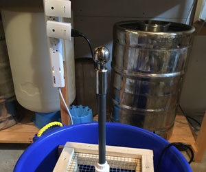
The heart of this bottle filler is a length of 3/16 inch ID tubing squeezed through a drilled screw top cap with a quick disconnect on one end. The disconnect can be attached to either the gas out line on a CO2 tank or (as shown) the beer out line on a keg. By attaching the filler to the gas and cracking the cap slightly, you can fill any screw-top bottle with carbon dioxide. Screwing the cap tight and disconnecting the gas line leaves it sealed at keg pressure.
To fill the bottle with beer, switch to the beer out line and slowly crack the cap on the bottle. This releases the pressure in the bottle and the beer flows into the bottom of the bottle. When full, quickly screw on a normal twist top cap and you’ve got carbonated, sediment-free beer ready to take to a party. What could be easier?
Home Bar

My pal Scott, the brewer at Harper’s Brewpub, outlined to me his idea for a very simple bar. The plan centered on a six-foot (2 m) counter top with 6” overhangs (150 mm) for knee and toe room. The surface would be 47” (119.4 cm) above the floor. When you plan your own bar, important considerations are: location of the bar, “elbow” height, surface cladding and plumbing for water and beer.
Elbow height, or vertical distance is critical. Whether you plan on standing by the bar or sitting on stools, estimate the best height for you to comfortably rest an elbow on a counter-height bar. Location will determine how many finished surfaces you will need. If one end is against the wall, you may not need to finish that surface.
Surfaces can be as cheap or expensive as you wish. Those of you who haunt the home stores know that pre-formed Formica-covered counter tops are inexpensive and come in a variety of colors.
The body (sides) of your bar can be covered with anything you choose. Scott and his wife, Sue, chose a prefinished sheet of paneling for all three sides of the bar.

Begin with an accurate drawing and be sure to allow for material thickness. For instance, if your counter top absolutely must be 47” from floor to surface top, allow for the counter top’s thickness.
In our project, we used a 2’ x 6’ counter (610 x 1830 mm). Overhangs are 3” (75 mm) on one side, 6” (150 mm) on the second side and 5 1/2” (139.7 mm) in front. This will allow knee and toe room around the bar. The sides are 42” tall and 16” wide and the front is 42” tall and 63” wide.
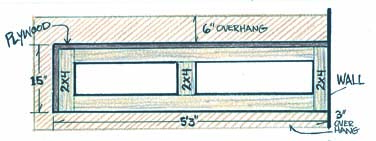

First, we cut the panels — front and side — from the decorated masonite sheet. With the sides and front cut, we cut the rails for three stressed skin frames. We chose to use half-lap joints and 2” x 2” select pine lumber. We cut six risers at 42”, two front cross members at 63” and four side cross members at 16”. All three rectangles were laid out on a worktable. A single pilot hole was drilled for each joint and glue was applied to the half-laps and fastened with a “deck screw.” Then the panel skin was applied with finishing nails and the nails lightly countersunk.
With all of your panels built, stand them on level ground and test the assembly. Clamp the panels together and, from the back, predrill pilot holes for 3” deck screws. Three should suffice. Check the overlap of the side panels and remove any excess.
To disguise the joinery, cut two 42” strips of 1/2” or 3/4” corner molding. You’ll later glue this to the corners to hide the exposed joint. Reassemble the front and side panels, using 3” deck screws. Set the counter top atop the panels and measure for overhang. Allow 1/2” so you can apply a finishing strip to the exposed end panels.

Attach the counter top to the panels. We chose to use 3/8” x 2” hardwood dowel pins. Drill 3/8” x 2” holes through the bar surface into the center of the 2” x 2” frame rails. Scott and Sue have two kids, a toddler and a 5-year old. Leaving corners on the front seemed a very bad idea. Using a 1-gallon (4-L) paint can as a template, we penciled an arc and cut with a jig saw. As a final touch, we decided to round over the edges using a router.
Remove the counter top and upend the structure. Because all floors are not level, install leveling feet. Drill holes of a size and depth specified by the leveler manufacturer. Screw the body of the leveler together, and bang in gently with a wooden or rubber mallet.
The last step before staining (optional) and applying a sealant — unless your décor runs to beer-stained wood — is to attach the draft tower (but that’s another project).
Draft Serving Freezer

The temperature in Ken Peters’ Oklahoma garage routinely climbs over 90 °F (32 °C) in the summer. So he set out to build a double-walled, insulated collar that would project 3” above the current height and slip over the walls of the chest freezer, which holds his Corny kegs. The 6” (15 cm) collar walls would be made of plywood, the top of pine and the finished shell will be stuffed with fiberglass insulation.
The first thing you need to do is remove the screws from the freezer body (not the lid). Measure both the inside and outside dimensions of the freezer as well as the thickness of the wall. Ken’s freezer had a recessed lip on the inside of the wall that made measurement tricky, so he clamped a piece of wood on each side and measured between the inside edges.

Start the actual construction by ripping the plywood (for the sides) and pine (for the top) to the correct width. The width of the pine will be the height of your collar (including overlap). The width of the pine should be the width of your freezer wall. Once all of the pieces are cut to the correct width, you will need to cut them to the proper length. The front and back outside pieces will need to be 1” (2.5 cm) longer than your measured length to allow them to lap over the ends of the side pieces. Additionally, add 1/8” (0.32 cm) to the length of all of the outside pieces. This will allow leeway for the collar to slip over the wall when completed. Once the new measurements have been determined, cut the outside pieces to length. Begin assembling the outer frame by clamping the pieces together and testing the fit over the freezer wall. The collar should fit snugly, but not bind on the sides. When gluing and nailing the front and back to the sides, remember to lap them over the ends of the side pieces. Once you have the outside frame completed, slip it over the freezer to ensure that it still fits. Measure and cut the top pine pieces to fit tightly inside the frame. As you cut a piece, glue and nail it to the frame. Be sure that the top of the board is flush with the edge of the plywood as they will need to be sanded flush.
Cut four blocks of wood from scraps to use as spacers for the top. These pieces will be used to hold the collar above the top of the freezer wall. Their size will be dependent upon how high you wish the collar to extend above the wall. In Ken’s case, he wanted 3” (7.6 cm) above the wall and 3” below. Two blocks will be placed in the front and two in the back. Ken used 1” screws to attach the spaces to the collar.

The next step is to assemble the inside pieces. A tight fit is required on the outside to limit airflow, but on the inside, more flexibility is needed to ensure that the collar will fit over the walls of the freezer. Consequently, leave 1/2” (1.3 cm) at each end of the front, back and side boards for leeway when fitting the collar.
Sanding the collar prepares it for a final finish and provides a smooth, level surface so the lid gasket can seal properly. Ken applied three coats of white latex paint to all surfaces including the inside.
Turn the collar upside down and, starting at any corner, carefully wrap the pipe insulation around the inside of the collar. Keep the insulation pushed to the top of the collar, flush
with the bottom of the spacer blocks.
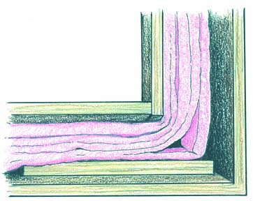
To install the collar, apply a bead of white, adhesive caulk about 1” below the top on the outside wall of the freezer. Then carefully place the collar on the freezer. Push it down until the spacer blocks all have come into contact with the freezer top.
Fasten the lid on top of the collar by driving screws through the holes on the hinges. To complete the project, all that is needed now is to install the probe for the temperature controller and CO2 lines through holes drilled near the middle of the back of the collar.
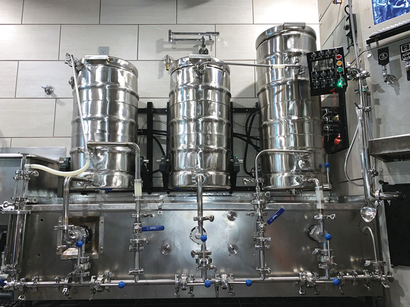
Peristaltic Pump

A peristaltic pump is essentially a pump that moves liquid by squeezing it through a tube. Most peristaltic pump designs are centered on a tube wrapped around a rotor. Rollers on the rotor “massage” the tube, pushing the liquid through. A peristaltic pump is gentle with the liquid being pumped compared to most other types of pumps.
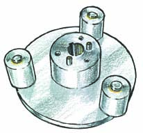
Mark based the idea of his pump on that of a medical peristaltic pump of his brother’s that was much smaller. He dismantled the pump to see how it worked and used his observations to design the pump with the help of some engineering software. The pump basically consists of a housing that holds the pump, a rotor that spins and three rollers attached to the rotor that “pinch” the tubing to the wall of the housing.

His brother’s pump was more complex in terms of electronics and, to some degree, in the design of the pump itself. Not needing all that complexity, Mark simplified the idea to what you see using basic volume calculations of liquid displaced between rotor tips for a given speed and pump diameter. He set a target of 8 gallons (30 L) per minute at an RPM well below posted critical speeds for a peristaltic. Information he found on the Internet stated not to exceed 400 RPM or the tubing in the pump would have a short life. So, he figured on using a speed at 1/2 to 2/3 this value (200–300 RPM). With those variables “set in stone,” he calculated the required diameter of the rotor assembly and the housing. The distance between the tip of each rotor and the housing when the rotor fully compresses the tubing was “guesstimated” at about 0.01 inches (0.025 cm) — less than twice the wall thickness of the Norprene tubing. With 1/16 inch (0.16 cm) wall tubing, the distance was 0.115 inches (0.29 cm).

After he finished the design, he fabricated the parts out of aluminum, assembled the pump and tested it with water. He ended up adding a strip of shim material to the inside of the pump housing to increase the “squeeze” on the tubing and got a perfect seal. The flow rate did not quite reach his target due to how he estimated the volume of liquid between rollers. He treated this volume as a simple cylinder, but in the real world the ends of the cylinder are crimped near the rollers, reducing the volume being pushed through the tubing. The actual amount wasn’t that different and came out close enough to use in his brewery.
The most difficult part of the project for him to build was the pump housing, which was made of five pieces of scrap aluminum bolted together. These pieces were CNC milled to the correct shape. (A CNC machine is a computer-controlled mill that makes precision cuts in metal.) It could have been made of a solid billet, but this would have been very expensive unless found in a scrap yard somewhere. Mark says that a plastic housing might also work. The pump is powered by a motor and when it runs, it makes a very rhythmic “ffft-ffft-ffft” sound. The hoses pulse and shake with the same smooth rhythmic sound. Mark says, “It’s really cool to watch.”
Peristaltic pumps are positive displacement (self-priming), the liquid does not touch the pump itself, and using a variable speed motor allows him to slow the flow rate without partially closing any ball valves in his brew system.
Part of the reason Mark built the pump was the challenge of doing something different from scratch. It also gave him practice in computer design and machine shop skills. He would like to acknowledge the folks in his homebrew club — the State of Franklin Homebrewers in Johnson City, Tennessee — for supporting his idea. For more on Mark’s brewery, see his website at users.adelphia-.net/~markvalk/brew.htm.