Project

Bottle Filling Station

Ever since my brother Brenton and I moved from bottle conditioning to kegging, bottling has become associated with foam volcanos and sticky floors. Since the beer is carbonated it made bottling a little tricky. With the recent expansion to 20-gallon (75.7-L) batches something had to change if we wanted to continue bottling our homebrew. One of our goals in this upgrade was to make as many aspects of our brewhouse semi-automated and more efficient.

This is when the idea of a miniature bottling line was born. We needed something easy to operate, with a compact design and durable material. Thankfully, my brother Brenton has taken the role of Lead Cooper in our brewery. A Cooper is the maker and repairer of all machines, systems, and vessels in a brewhouse. He’s the guy who says “hold on, I can make something for that.” Two weeks later BOOM! With ingenuity we are slowly automating our entire homebrew setup.

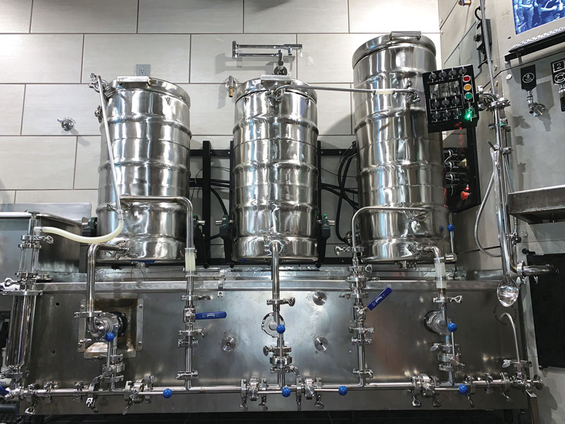
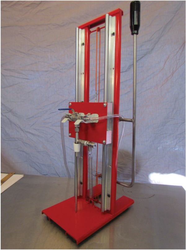
After doing some research on commercial bottling systems, we tried to incorporate a few of those design elements into our version. Each commercial system purged and filled multiple bottles without any foam. They all move vertically as the new bottles move into place. This was a bit of a design challenge trying to make the filling components move up and down instead of having the bottom platform adjusting each time you fill a bottle. The advantage here is you do not have to adjust for each bottle. The system stops when it meets resistance from the bottle allowing for any size bottle to be placed in line for fill at anytime. We also wanted it to work off a table top and not require mounting so it can be easily put away when you are finished. After several trips to the hardware store and our local metal shop, we started to build.

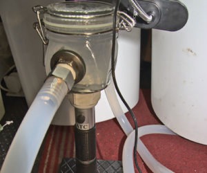
The bottle filling station is based around a counter-pressure bottle filler, which can be purchased from many homebrew shops. The basic framework for this operation allows for the bottle filler to be mounted onto a sliding rail system. The slide moves up and down to fit any bottle. If you change out the bung you can fill growlers too. The spring loaded handle maintains a constant seal which keeps the CO2 in solution. After purging the vessel of oxygen, fill it with delicious homebrew.

After making the first concept model we invited some friends over for our next brew day to see if the filler was intuitive enough for anyone to use. If our friends are anything like your friends, they are much better at consuming the beer than helping make it. The bottler was a hit and most of our friends are now competing for the bottling position on brew days.

Alright enough talk, let’s do this!

Tools & Materials

TOOL LIST
Welder
Magnetic welding assistants
Cut-off wheel
Drill or drill press
Measuring instruments
Tap and die set

PARTS LIST
1 ft. (31 cm) of 1 in. (25.4 mm) wide C bar metal stock
6 ft. (183 cm) of 2 in. (51 mm) wide C bar metal stock
4 mm round bar stock (pulley shaft)
1⁄16 in. (1.6 mm) round stock (L bracket)
4 ft. (122 cm) of 3⁄8 in. (9.5 mm) round stock (lever)
1.5 mm deep V-pulleys (4 mm ID x13 mm OD x 6 mm width)
5 ft. (152 cm) of 1⁄16 in. (1.6 mm) stainless steel cable
6 in. (15 cm) medium duty spring (8.5 lbs./3.9 kg working load)
16 gauge sheet metal. Enough to make 5 in. X 7 in. (12.7 cm X 17.8 cm) and 6 in. X 7 in. (15.2 cm X 17.8 cm) squares
D loop rope attachment
Rail system: 12 mm X 500 mm shaft, 12 mm slide blocks, 12 mm slide bearings
Automotive-style stick shift handle
1⁄4 in. (6.4 mm) – 20 nuts and bolts
3⁄8 in. ID X 1⁄2 in. OD (9.5 mm ID X 12.7 mm OD) flanged brass bearings
1⁄2 in. ID X 7⁄8 in. OD X 2 in. (12.7 mm X 22.2 mm X 51 mm) bushing
(2) Spring loaded broom holders (holds the counter pressure bottler)
Counter-pressure bottle filler

STEP 1. FILLER PLATE Mount the 5 in. X 7 in. (12.7 cm X 17.8 cm) piece of sheet metal to the blocks on the sliding rail. Then drill mounting holes 1⁄4 in. (6.4 mm) from each edge. Use the screws to mount the plate to the blocks on the rail system. This is the part that will later hold the bottle filler. Take your time to make sure everything is square and evenly spaced so the rails are perfectly parallel. Pre-drill your holes in the center of the plate for the spring loaded broom grips that will hold the bottle filler. Mount them after the framework is built.

STEP 2. FRAMEWORK Weld the upright C bars 6 in. (15.2 cm) back from the front to fit the base plate. You will want to make a perfect 90 degree angle. We used 90 degree magnet holders to assist. The vertical bars measure 25 in. (62.5 cm). The base bars measure 11 in. (279 cm). The base will be a 6 in. X 7 in. (15.2 cm X 17.8 cm) piece of sheet metal. Moving forward, we will refer to this as the framework.

STEP 3. MOUNTING THE RAILS To attach the rail system to the framework, mark and drill the two holes on the top and bottom of each rail. We made this attachment with 8 nuts and bolts. As you are lining up the rail system for mounting the middle of the filler plate will need to travel lower than the height of a 16-oz. (9 in./23 cm) bottle and the top will need to be high enough for a 22-oz. (11 in./28 cm) bottle to fit under the bottom of the filler tube. The rail travels 500 mm or 19.5 in. in total giving you plenty of movement for all sorts of bottles to fit.

STEP 4. BASE PLATE AND TOP SUPPORT Now that the width has been set, measure and cut a piece of the 1-in. (25.4-mm) wide C bar to connect the two upright frame pieces. The gap should be around 7 in. (17.8 cm) apart from the outer edges. Weld the underside edges together. Do the same for the sheet metal that will become the base plate. This will be where your bottle sits. As you are joining the two sides make sure you are sliding the filler plate up and down looking for any tight spots. Using clamps to hold everything in place before welding is a must.

STEP 5. LINKAGE Take the 1⁄8-in. (3.2-mm) round stock and cut two sections to span the distance between the framework for your pulley to mount. This should be around 4 in. (10.2 cm) long. Make sure you slide the pulley on before welding in place. Mount them 1–1.5 in. (25.4–38.1 cm) from the top and bottom of vertical bars. Take another section of round stock and bend it into an L shape with a cross member to support the cable attachment. Weld this to the back of the filler plate. This will also serve as the top point of attachment for the spring. Finally, weld the rope loop onto the base between the upright bars. The cable will anchor at the L bracket, travel to the top pulley, down to the bottom pulley, and terminate on the bottom of the hand lever. The rope loop will be mounted in between the vertical bars on the base plate and will be the bottom point of attachment for the spring.

STEP 6. HANDLE CONSTRUCTION Cut a piece of 3⁄8-in. (9.5-mm) round stock 36 in. (91.4 cm) long. Bend into L shape. The bottom of the L should be 6 in. (15.2 cm) long before it travels up to the handle. Cut a separate piece of round stock that is 4 in. (10.2 cm) long and weld this on 8.5 in. (21.6 cm) from the bend in the lever. This will be the pivot point for the lever. Weld a sleeve for the bushing halfway up the right-hand side on the back of the frame. If you are left handed do this on the opposite side. Drill a 1⁄16-in. (1.6-mm) hole for the steel cable to tie off to in the middle of the frame. Attach the handle of your choice to the top of the bar. Depending on your choice adjust the overall height. We used an automotive stick shift handle. Mount the broom holders to the filler plate, making sure the filler tube stops 1-2 in. (25.4-50.8 mm) above the base plate. Let’s start bottling.

Issue: January-February 2018