Project

Water Control System: Making the most of a float switch

One of the things that I enjoy about homebrewing is customizing my brewing system. I have built several contraptions to help improve the quality of my beer, make brew day go more smoothly, and reduce the risk of the mishaps that can add unneeded frustration. One of the things I built with those goals in mind is my water control system.

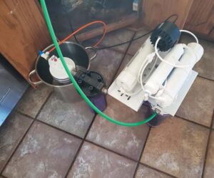
The water control system helps with three aspects of the brewing process: Filtration, hot liquor tank (HLT) fill, and sparging. First, the system filters the chlorination from the tap water. Second, it controls the water level when the HLT is being filled, automatically shutting off the water flow when the set point is reached. (Ever had a time when you got distracted and overfilled the hot liquor tank?) Third, during sparging, the system maintains a constant level of water in my mash/lauter tun (MLT), preventing the grain bed from inadvertently running dry.

The water level control assembly consists of several parts. There is a T-shaped frame of PVC pipe that sits on top of the HLT or MLT. Through a hole drilled in the T-frame, a piece of CPVC pipe is friction fit perpendicular to the T-frame. The CPVC pipe serves as the water level adjustment rod. At the bottom of the adjustment rod is a float switch. Slide the rod down through the cutout in the T-frame until the float switch is at the desired water level. Because the adjustment rod is tightly held in the T-frame, the float switch stays at the water level set point.

When the HLT is being filled, the float switch control sends a signal to a relay to open a solenoid valve, then closing when the float switch is triggered by the water. The solenoid valve that I used is from a dishwasher, but a dishwasher solenoid needs to be properly enclosed. Other kinds of valves, such as the 12V stainless steel solenoid valve listed below, would also work. When it is time to sparge, the water level control assembly is moved to the MLT, and the float switch now controls power to an electrical outlet into which my brew pump is plugged.

The control box is where the connections are made amongst the main electrical components. I used switches to turn the solenoid valve on to start the HLT fill and to turn the pump on and off for sparging. The control box includes an electrical outlet into which the pump is plugged for use during sparging. It also includes a connection from the float switch on the water level control assembly. I also used a 12V power supply because of the risk of running 120VAC current into the tank, and because most float switches are only rated for less than 50 volts. Be sure to cover any exposed 120VAC conductors inside the electrical enclosure.

Tools and Materials

  • 1⁄2-in. NPT stainless solenoid valve (U.S. Solid USS2-00069)
  • Float switch
  • Relay
  • 15 amp marine inlet
  • Electrical enclosure box
  • Control switches
  • AC to DC power supply 12V 5A 60W
  • 15 amp electrical outlet
  • Water filter
  • Length of PVC and CPVC pipe
  • (1) PVC T-fitting
  • (2) CPVC endcaps
  • Silicone sealant
  • Wood and screws for building the mounting board
  • Miscellaneous wire, terminals, fuses, and electrical components
  • Conduit and connector
  • Saws for PVC pipe and wood
  • Drill or drill press, drill bits
  • Wire cutters

*Brewing with electricity can be hazardous. There is a risk of electrical shock or death. If you decide to build this system, your design and finished project should be reviewed by a licensed electrician. Any 120VAC power used in brewing operations should be protected by a Ground Fault Circuit Interrupter (GFCI).

1. Water Level Control Frame

The diameter of the PVC pipe (certified for potable water) for the T-frame must be large enough such that a hole can be bored for the adjustment rod to pass through. I built the T using three pieces of 3⁄4-in. (OD) PVC pipe and the appropriately-sized 90° T- joint. Cut the PVC pipe long enough so that can be used with both your HLT and your MLT. I used 1⁄2-in. CPVC pipe, which measures 5⁄8-in. OD, for the adjustment rod. Make the rod long enough so that it will reach to near the bottom of the HLT and MLT. Drill a hole through the PVC T-frame, perpendicular to the plane of the T, for the adjustment rod. The hole needs to be centered and located so the adjustment rod will be over the middle of the tank. The hole you drill needs to provide a snug fit, so that the adjustment rod will be held in place by friction at whatever level you set it. The T-frame can also be set up to hold the tubing for filling the HLT and the sparge arm for the MLT.

2. Wiring the Float Switch

There are numerous online sources for float switches. I recommend using a marine-grade switch like a bilge pump float switch. Be sure that it is rated for temperatures that will be seen in a MLT.

Drill a hole in the center of each of two plastic caps sized to fit over the end of the adjustment rod. Fit the float switch through the hole in one of the caps so the wires can be threaded up into the adjustment rod.

From the float switch, the wire runs up the length of the adjustment rod into the enclosure. For my cable that connects the assembly to the electrical enclosure, I fitted the cord through the hole in the second plastic endcap and threaded the cord down through the adjustment rod. Seal the endcaps in place with silicone sealant; alternatively they could be glued in place.

3. Wiring the Electrical Enclosure

Float switches are always low-voltage devices, so you will need a 12V power supply and a relay. I also recommend using a 12V solenoid valve for several reasons. Always make sure that whatever electrical devices you use are UL listed, and are rated for the voltage and current that they will be expected to carry. The relays, outlets, and switches should be mounted in an appropriate enclosure, and always make sure that proper grounding practices are followed.

4. Building the Mounting Board

The filter, solenoid, and electrical enclosure need to be mounted to something. I built a wooden stand for this using pieces of plywood and lumber that I had on hand and ended up with the structure you can see in the picture at right.

Mounting these elements on a wall would be a good option as well, securing them in place. I wanted this to be movable though. If you build this, be sure to keep this well out of your way while brewing. You do not want this to tip over.
My plywood backer board measures 42 in. x 19 in. x 5⁄8 in. (107 cm x 48 cm x 1.6 cm). The two vertical supports are 5 feet (152 cm) long, and were made by ripping a 2×4 (48 mm x 98 mm) in half on the table saw. The two feet that rest on the ground are 24 in. (61 cm) lonthe g. The feet are braced to the vertical supports with pieces of 2×4 (48 mm x 98 mm) ripped in half and mitered at 45 degrees at each end. Once I had the mounting board assembled, I covered it with a couple of coats of polyurethane.

5. Selecting the Water Filter

I have used two different styles of water filters. I initially used an in-line filter from a refrigerator ice maker/water system. I later upgraded this to a single stage under-sink water filtration system and replaceable carbon block filter. I don’t have any problems with sediment in my water supply, so single stage carbon filtration meets the need to remove chlorine and chloramines from my brewing water. I recommend 1 gallon/minute (3.8 L/min) or less for proper de-chlorination. It is slower for chloramine removal though. If you have issues with sediment, you could use a two-stage filter system, with a sediment filter in series ahead of the carbon filter.

6. Mounting all of the Parts

When I arranged the components on the mounting board, I wanted the electrical enclosure to be above the solenoid and filter, so that any water drops from leaks would not fall onto anything electrical.

Once you have the solenoid and filter in place, run PVC tubing from your water supply to the solenoid, and from the solenoid to the filter. You will also need a piece of tubing to run from the filter to your HLT.

Issue: November 2019