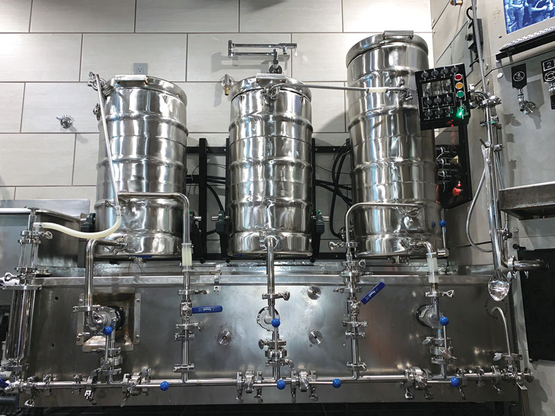
Build a Heated Mash Tun: Projects
Mashing is one of the most defining steps of the brewing process. This step will define the fermentability of your wort and affect mouthfeel, flavor and even head retention of your beers. This was the reason why I started looking for precise and accurate mashing equipment.
My first attempt to control my mash temperature was done by direct flame heated mash, but I found that it often had hot spots and temperature overshoots. It also needed constant attention. The typical ice chest is an easy and tempting route but I like to be able to execute temperature program mashes if I need to, and don’t like to have to dilute the enzymes with water by hot water additions as I feel that in itself is a source for variability. I looked into brewing using a re-circulated infusion mash (RIMS). However, I could never get comfortable with the idea of pumping hot wort around for a whole hour or more. Under the stress of a centrifugal pump, I believe any oxygen in solution will react to oxidize the wort. Also, mashing enzymes are much more heat sensitive in a thin mash, and that is exactly the kind of environment that enzymes are exposed to when wort is being re-circulated through a heater element outside of the mash tun. At that point I moved on from RIMS and this eventually led me to the mash system that I am about to describe.
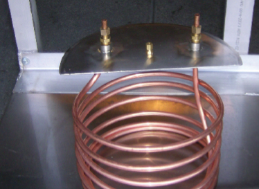
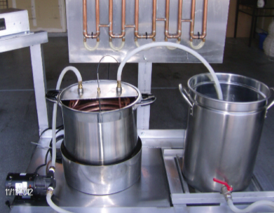
I built a coil-heated mash tun that closely resembles the mechanism of mash mixing vessels that professional brewers normally use. This system uses a large copper coil heater, evenly distributed throughout the inside wall of the mash tun. Hot water from a regular hot liquor tank (HLT) is pump re-circulated through this coil and back to the HLT. This process is regulated by a PID temperature controller that turns the recirculation pump on/off as the heat is demanded by the controller to keep a repeatable temperature within 1 °F (0.5 °C). A heater coil throughout the mash tun at a low temperature differential provides gentle heating to the content of the mash tun, while at the same time being capable of executing a temperature program mash adding heat at a controlled rate of 2 °F (1 °C) per minute.
Editor’s note: This project requires electrical wiring. Do not attempt electrical wiring projects unless you are experienced with electrical wiring as mistakes can cause serious physical harm. Ask a licensed electrician to help you if you are not comfortable with electrical wiring.
Parts & Equipment List
- 20 feet copper coil (or enough to provide full coverage of your mash)
- Mash tun equipped with false bottom and drain valve
- Two 3⁄8 NPT by 3⁄8 compression fittings
- One 1⁄8 NPT by 3⁄16 compression fitting
- Six feet (or shorter) grounded electrical extension cord
- PID temperature controller
- Thermocouple probe 3⁄16 sheath size by 12-inch (30 cm) long to match input signal for PID controller (in this case type J thermocouple)
- One solid state relay (SSR) at least 4 amps, assuming your pump pulls less than 2 amps
- Recirculation pump suitable for hot water
- 10 feet (± depending on the layout of your set up) of silicone high temperature hose
1. Create the Heater Coil
Create the heater coil and secure it onto the lid of the mash tun for top entry. To secure the coil ends to the lid I used 3⁄8 NPT by 3⁄16 tube adapters. For the lid, I recommend leaving at least half-open spacing for you to be able to hand mix the mash when going up in temperature for a step mash. I also found it easy to secure the thermocouple on the center of the mash lid using a 1⁄8 NPT by 3⁄16 tube adapter.
2. Attach the PID Controller
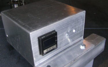
Attach PID controller and SSR to the mounting panel. I built mine using a 5-inch (13-cm) piece of aluminum framing material and sheet metal. An easier and more elegant option is to buy the appropriate box for a 1⁄16 DIN controller off the shelves. I have seen them online for around $28.
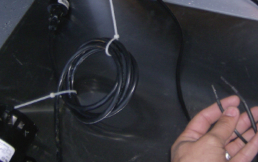
3. Prepare
Prepare extension cord to power recirculation pump by installing slip connectors. These slip connector ends attach to the output side of the SSR (right side terminals in SSR image). The electrical extension cord connects to the wall power outlet on one side and to the recirculation water pump on the other. The electrical connections from slip connectors to SSR must be properly secured inside of the PID enclosure. Also, if the PID enclosure is made out of metal the equipment ground from the extension cord must be attached to the metal housing. This can be done with a grounding bus, or a pigtail to a grounding bolt.
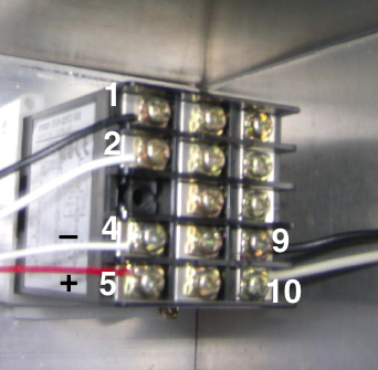
4. Connect the Thermocouple
This figure shows the wiring for the particular PID controller that I am using (Omron E5CN). Connect the thermocouple to input side of PID controller (terminals #4 and 5 in photo). Connect 110-volt power to PID controller (terminals #9 and 10). Connect output terminals of PID controller to input side of SSR (terminals #1 and 2).
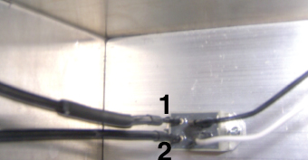
5. Wire the Solid State Relay
Connect the output terminals of PID controller (terminals #1 and 2 from PID) to the input side of SSR (black and white wires on the right side). Connect the slip connectors from power extension cord to pump to left side terminals of SSR (output side).
6. Connect the System and Test
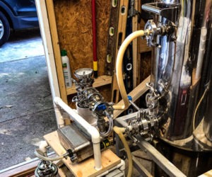
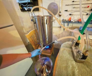
Measure and cut the length of silicon hoses necessary for hot water recirculation loop. The drain valve of the HLT connects to the inlet side of the water pump. Attach the outlet side of the water pump to one side of the copper heating coil in the mash and connect the other side of the coil to return water to the HLT to be re-heated. Before brewing an actual batch of beer, test the system with water to familiarize yourself with its use. The owners manual of your PID explains how to set up the unit, however, the most important thing is to make sure that the PID is set up for the correct temperature probe. You also have to make sure that the temperature range in your PID’s settings covers the temperature you plan to use.
As a final note, this system takes hot water from HLT (hot liquor tank) and pumps it through a copper coil placed inside of the mash tun to add heat for a constant temperature or step mash. The pump is controlled by the PID so it will only run to add enough heat to the mash with little to no overshoot. The HLT does not need to be regulated but it must be higher than the desired mash temperature.
