Build This Brewstand
I’ve often praised homebrewing as one of the few great hobbies that combines the technical specificity of science and the spontaneous creativity of art. As a structural engineer having personally experienced the allure of homebrewing, I’ve also noticed the specific draw that brewing often has on the technical-minded individual. After all, modern brewing is an industrious process that requires a working understanding of many mechanical devices, process techniques, liquid transfer/routing, and number crunching to get that final intended volume/gravity/ABV. All of these lessons can scale down and start to be learned at the homebrew level; and they can be as complicated as you choose to make them. It is that last sentence that got me into trouble; because it wasn’t long after I began homebrewing that I convinced myself that I needed to design my own brewstand.
This desire stemmed from my experiences since starting homebrewing seven years ago, having lived and brewed in five different cities, where each location required me to adjust some small aspect of my routine. I also found myself being too spread out, running back and forth from room to room and inside to outside, which divided my attention and would sometimes result in recipe oversights or the occasional boil-
over relocating half of the hop leaves to the outside of the kettle. A brewstand would not only consolidate my area of work on brewday, but the process consistency would allow me to develop consistent recipes and baselines for fine-tuning. This was something I dreamt about for five years until living conditions were such to usher in this new era in my homebrewing.
I will say first and foremost that there are numerous brewstands available commercially that are creative, gadgety, and definitely something I wouldn’t say no to if somebody offered me one. The goal of this project was not to save overall money. While the final material/equipment take off was just under $3,500, the amount of time spent for design, drafting, and fabrication is definitely not reflected in the final cost (but keep in mind this can be a project that spans many months or even years, so the time investment is spread out). The true goal, like most do-it-yourselfers, was to learn through doing and tailor things to my personal needs. Homebrewers by nature are often very DIY-minded and so, coupled with my engineering background, there was a clash of curiosity and desire that begged the obvious question: How can I not build this?
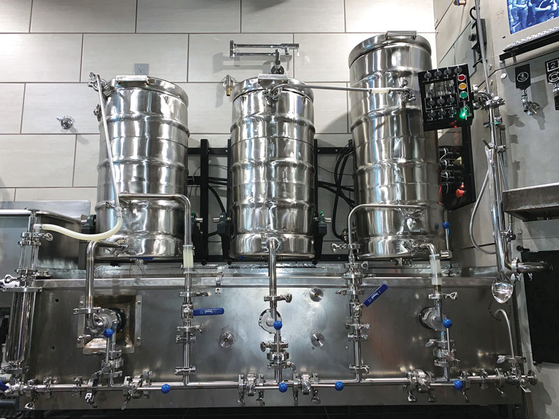
The very first thing I did was sit down and look at the standard designs of commercial brewstands, noting the features that I did and did not like, in order to develop the conceptual framework for the build. My design would be a steel-frame hybrid 2-tier RIMS (recirculating immersion mash system), as I preferred the eye level operation of lateral systems in tandem with the gravity-fed lautering of tiered systems. I limited my system capacity to 10 gallons (38 L), which would allow me to experiment with multiple carboys/yeasts or to experiment post-fermentation with 5 gallons (19 L) and various dry hops/additives, and still have 5 gallons (19 L) of base beer to go directly to the keg. I also considered that at the homebrew level it becomes more difficult and time-consuming to drink/keg/bottle and give away 10 gallons (38 L) of each batch you brew.

I sized each vessel to accommodate a 10-gallon (38-L) batch of high-gravity beer (15-gallon/57-L boil kettle, 26-gallon/98-L mash tun, 10-gallon/38-L hot liquor tank), since I did not like the commercial standard to use three equal-sized vessels. I mean, why would the hot liquor tank ever need to be the same size as the mash tun? Similarly, I felt the need for three burners was excessive, as liquor could simply be heated in the boil kettle during the mash and pumped to the hot liquor tank (HLT) (essentially a holding tank) just prior to performing the fly sparge/running off from the mash tun to the boil kettle. If the HLT is jacketed I believe there is enough leeway in the range of allowable sparge water temperature to accommodate the heat loss in the holding tank that occurs over the course of the sparge. Economy of materials clearly influenced my preferences, since I feel one of the benefits of DIY projects is to pay less overall money (even if paying far more in time).
The finer design details and build procedures are broken down into the following steps to provide a general approach that anybody can follow in the design of their own custom brewstand. I will say ahead of time that, due to the iterative steps necessary to converge on final design dimensions, the aid of a computer drafting program (I used AutoCAD) will make your life a whole lot easier. I will explain the stages with regard to my build, but the underlying process of each step will equally apply to your own customized creation.
STEP 1. Conceptual Sketch of Unit and Features

The purpose of this stage is to focus on global constraints (i.e. overall unit length, maximum height of each tier, etc.), which also indirectly determines your level of adjustability. In my case, sketching the initial layout showed me needing a stand that was approximately 6-feet (1.8-m) long. However, my storage space consists of a nominal 8-foot (2.4-m) wide brew shed (which can be seen in the “Equipment Mods” article in the July-August 2019 issue of BYO). While the total stand length would technically fit wall-to-wall, it was not practical when considering having to move around it to access shelving/wall-mounted items. Therefore, I moved forward with a design that incorporated a retractable lower tier, which I expanded upon to create a tilt up design for transportation.
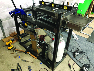
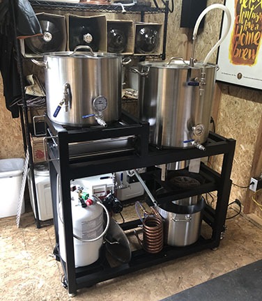
Note that steel tends to be pretty heavy. I’m a pretty big guy so I puffed up my chest and said “bring it on” . . . I was wrong (cue chest deflation). In order to comfortably tilt and move the stand as shown in the photo to the left, the kettles need to be removed before transport. The configuration shown is what I utilize for storage, which works very well for consolidation of equipment in my limited space. The clearance/space for the HLT storage was one of the projected constraints from the conceptual stage that governed part of the design (see Step 2). After considerations were taken for brewing process, component layout, and rough overall dimensions, the next step was to acquire the various brewing components for measurement and relative placement.
The last takeaway from Step 1 is to remember that your initial numbers will likely change, but the idea is to give yourself a template and make your concept feasible, leaving enough wiggle room for later necessary adjustments.
STEP 2. Component Measurements and Geometric Layout

This stage took me over a year, since I partly relied on birthdays and Christmas presents to acquire all of the necessary brewing components, whereby I could then get accurate as-built measurements. I have found that trusting the measurements provided by a website can be a recipe for failure, depending on how much space for adjustability you build into your design. While website measurements are often in the ballpark, if you are dealing with small clearances or tight fit-ups then you need to know the exact numbers (it’s a “measure twice, cut once” mentality that will come up again later in this article).
Once I had specific diameters, heights, and structure member sizes I was able to position items and confidently put numbers to my initial design concept. This process of relative placement within a specified overall constraint “envelope” involves trial and error, as numbers get fine-tuned and problems with initial concepts arise and require a different approach. Drawing and locating the component boundaries to scale is very important; not only to identify interferences, but also to pass the visual test, meaning “does this look right?” For example, I chose to primarily use square 1⁄8-inch thick tube steel that measured 2-inch x 2-inch (5-cm x 5-cm) cross sections because it looked proportionally better; as opposed to smaller member sizes that could have easily worked from a strength standpoint. I performed a structural analysis of my stand (just for fun, because I’m a nerd, as I knew it was inherently fine) using various software and the maximum member stress came out to 9% of allowable capacity. So, I could have safely used smaller square tube steel, but again, I liked the look of the thicker size. The development from Step 2, more than any other step, will influence the final product; so it’s good if you go slow and get it right.
Have fun with the true genesis of your design, and remember that one of the benefits of custom projects is customized conveniences. For example, my layout accommodates a sliding drawer under the HLT (see image from Step 1) that is convenient for putting future hop additions, gloves, or other miscellaneous items on.
STEP 3. Design Drawings And Material List
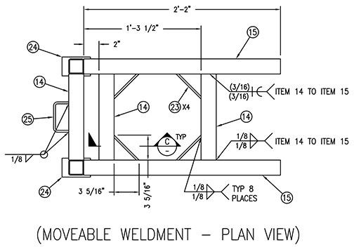
This image indicates the difference between the layout drawing from the previous step and design drawings. While my layout drawings showed the overall assembly dimensions, these drawings mainly serve to assure the functionality of the build, which influences how things get supported. Design drawings contain all the necessary information to physically build the supporting structure. Design drawings include such items as bubble call outs for specific members, member locating dimensions, and weld callouts. The material list will then contain member cross-sections, lengths, quantities, and material types, as well as quantities and information for required fasteners and miscellaneous items. Following the 2D layout of the stand, I located frame bracing in the 3rd plane (making the design a 3D space frame). These cross members served as members for structural stability, brewing component support, or both. It is at this time that I also routed a gas line to feed my two propane burners and quantified the required parts in my materials list. Prior to material procurement, your design/material/weld details should be checked by either an engineer or experienced individual who understands structural stability and the materials being used.
STEP 4. Fabrication AND Preliminary Fit–Up
Once you know all your member lengths for your metal frame, you must determine the quantity of transportable lengths to purchase from a metal supplier, from which your members will be cut. The total length of metal does not equal the total length of metal you order. For those who haven’t spent a lot of time building things this may sound like obvious advice, but I guarantee a lot of people have made this mistake. You must lay out exactly which length piece each of your members will be cut from. Organization is the key here because you don’t want to cut the wrong members from the wrong purchased pieces.
Depending on your available resources, you may wish to have the supplier or fabricator cut the items for you — to which you want to make it clear as day for them to know how to cut each piece.
For my build, my uncle is a machinist with an at-home metal shop, where I had access to a metal band saw for cutting members to length. If you’re unfamiliar working with metal, as I was, it is very helpful to research or have access to a credible resource for metalwork. Machinists are incredibly handy people to know, so try and befriend one. My uncle helped me with miscellaneous other parts of this build, such as milling out notches in lids or drilling holes through hardened steel.
After all of the cuts were made, it was time to begin welding. I was yet again lucky enough to have an extremely valuable resource in the family to aide in fabrication (this work can be hired out otherwise). My father-in-law is a welder with a TIG welding setup and access to Weld Procedure Specifications for the metal types/grades and electrodes that we were using. It took us numerous weekends for fit-up, grinding, and tack welding, followed later by the actual design welds (see photo at top left).
Remember earlier when I mentioned the “measure twice, cut once” philosophy? Well, when you don’t abide by that rule, you can run into an instance where we have to cut structural welds because the legs on one end of the frame are an inch (2.5 cm) out of square. We used a reciprocating saw to remove the entire upper part of the frame, cut welds at the bottom of the legs, pulled the legs back into square and re-welded the upper frame. Tensions ran high that day and unfortunately no photo was taken because that’s the last thing on your mind after
massive failure.
However, with that speedbump behind us and the stand fully welded, I fit-up all the mounted brewing components in their intended mounting locations and matched drilled holes where required.
STEP 5. Powder Coat AND Final Assembly
With the frame welded and holes drilled, the final step was finishing. The primary metal option for commercial homebrew stands is stainless steel, whereby a finish is inherently not required. However, in keeping with my economical approach, going with stainless vs. non-stainless steel would have nearly tripled the material cost. Therefore I chose to contrast the brushed stainless of my brew vessels with a flat black powder coated finish on the frame. Powder coating is relatively cheap and offers a high-temperature option that has a listed durability of up to approximately 600 °F (315 °C). While it is not stainless, a black brew stand also has a sharp look to it.
After a few long awaited and satisfying final assembly hours, I had the customized beer makin’ machine that I’d been dreaming of for five years.