Brutus Ten Build
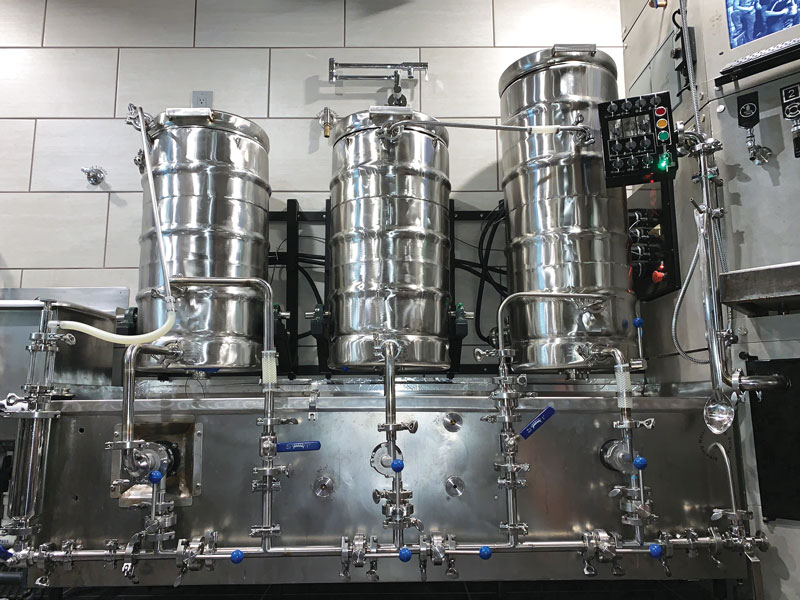
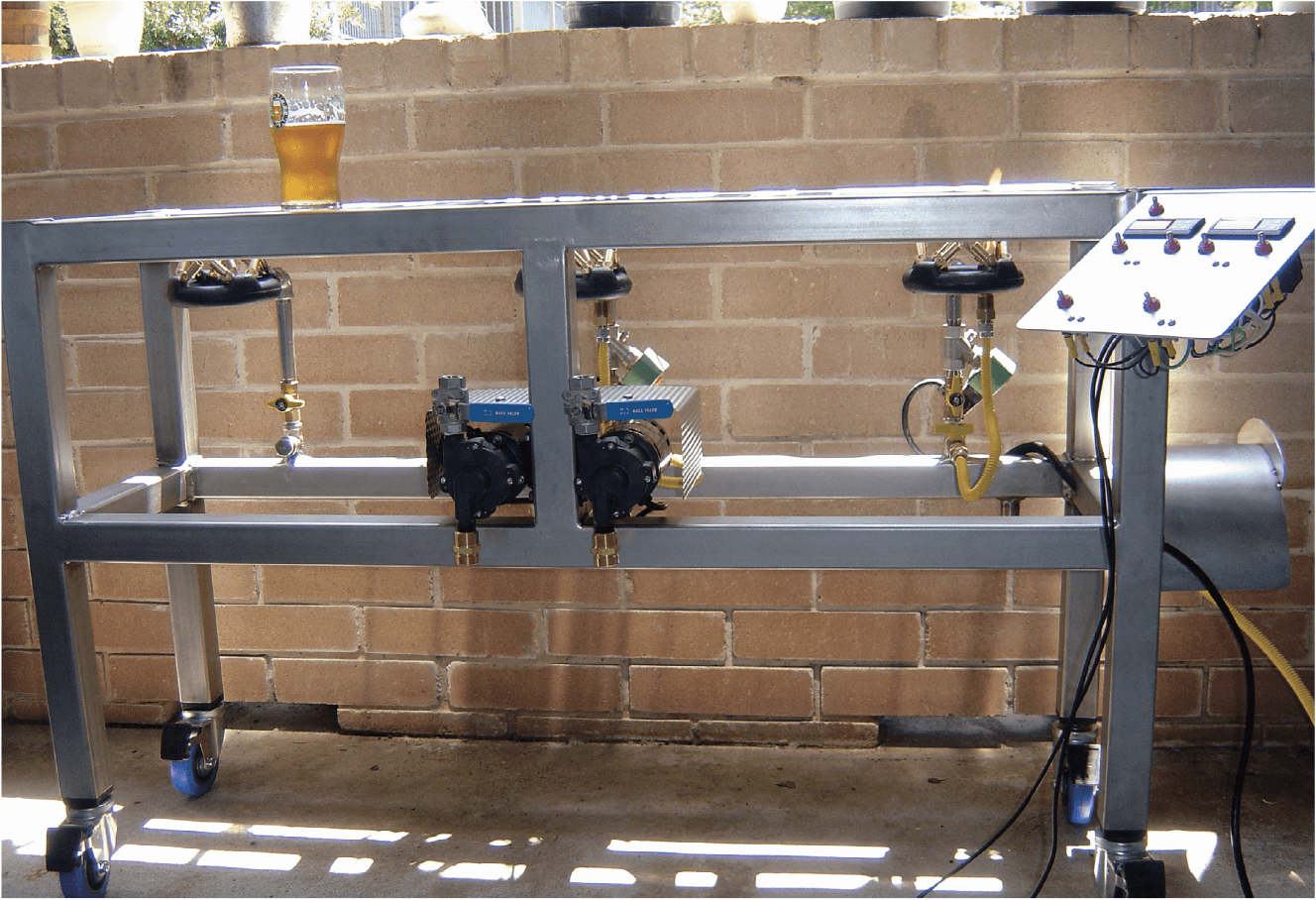
See my cool brewery? I call it Brutus Ten. If you’d like one just like it, I have just one thing to say — build your own! Heck, I’ll even show you how.
Brutus Ten is a 10-gallon (38-L), single-tier brewery situated on a stainless steel frame. The temperature of the hot liquor tank and mash tun are maintained automatically by two temperature controllers. Other aspects of the brewery, such as turning the pumps on and off are done manually. If you know how to weld and have some basic electrical skills, you can make your Brutus Ten for under $2,500.
You don’t need a ton of space to do this. I built Brutus on my living room carpet and my small 6’ X 8’ apartment patio. The raw stainless steel alone stretched across the threshold, from the dining room to the patio door. I hooked up a 220-volt welder to the dryer outlet. During the daytime, no one knew that, beneath the blinding flashes illuminating the whole complex, lay the birth and free-will-victory that is now Brutus Ten.
From Brisbane to Anchorage to Baghdad to Choupiqué, other Brutus systems are popping up everywhere. It humbles me to see that others are building their versions of Brutus. Here’s how to build yours.
Specifications
Mash: Direct-fired mash (Recirculation heat)
Controls: 2 each ASCO Red Hat stainless 1⁄2” NPT solenoid valves (Model SC8210G37)
Temp Control: 2 each LOVE TS temperature switches (Cole-Parmer EW-93520-00)
Fire: 3 each 100,000 BTU low pressure burners and low pressure regulators
Material: 2” X 2” X 0.120” wall 304 stainless steel
Weight: 210 lbs. (95 kg) dry, everything ready to roll
Fluid Dynamics: 2 each March pumps — high temperature polysulphone
Boil Capacity: 13.5 gallons (51 L)
Mash Tun Capacity: 33 lbs. (15 kg)
Finish Volume: 11 gallons (42 L)
Voltage: 110V
Planning
You know with a full keg and an enthusiastic welding pal, you can pave your way to your own version of your brewing vision. I am a tinkerer, a quasi-welder, a semi-electrician, a hydraulics-smithmen and though my very first real mash was sparged with a plastic bucket affixed to the roof of my rickety house seven years ago, even then I knew that it wouldn’t stop there. Though my plans for anything usually reside in my head, I first crafted Brutus Ten in a 3D CAD environment down to the last bolt. There is nothing like a visual before cutting begins. I probably spent more time in CAD than the actual build, but this method of calculation and foresight gave me time to really think of my brewing wants. Everyone needs a good plan and of course mine didn’t re-invent the wheel, but there are a few innovative features that Brutus sports. If only born from necessity, they insure a great consistent brewing day. With total consistency, I can make the same great beer over and over. Likewise with the bad! I found that once I had a plan, the hardest part really was procuring all the items that I needed for the build. This was quite a task of looking, finding, ordering etc. A lot of footwork went into the small list of up-front items purchased, but it all came together in the end!
Design
For the central design phase, I kept in mind brewing space limitations; I envisioned a small foot-print device, yet a traveling brewery for the occasional Mashtronaut brew-in. (The Mashtronauts are my Houston area homebrew club.) This brewery would be an all-in-one crescendo of semi-mechanized automation, yet again still leaving the fun in our brewday. It would be mobile and docile, maintain its gorgeous looks and yield great beer without the hassles of carboys, iodophor, or other means of cold sterilization. The first design task would be the only automation I would care to fit into any brewing scheme — temperature control!
It’s All About Control!
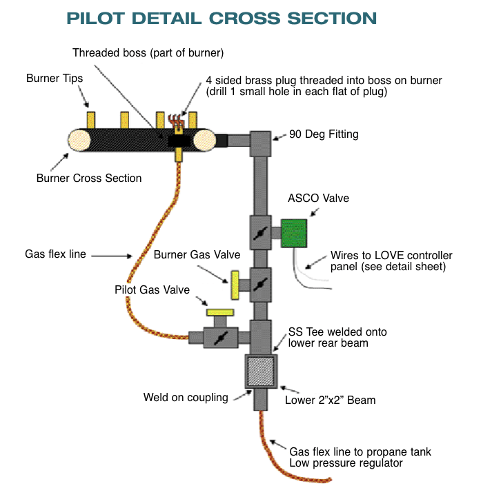
Mash and sparge temperature control, as important as it is, is taken care of with a most simple device; ASCO Red Hat solenoid valves under each the mash tun and the HLT. These handy little gadgets are nothing more than fancy switches. Built on stone-age principals, the ASCO gas valve requires only one simple thing; something to tell it when to open, allowing the gas to flow to the burner. Likewise, when a signal tells it to close, it shuts off the gas flow. The signaling is accomplished with the dynamic little LOVE TS switches; my favorite feature-packed temperature controller. The LOVE TS switch is simple in its operation. It opens, allowing power to flow to the ASCO valve, and turns off when the set temperature is reached as sensed by its temperature probe, just like a Ranco or Johnson controller would do. These little devices cost about the same, and have a ton of features crammed into its little stout frame. To get this setup to work, there needs be to one constant; a pilot light! I should say first that with any pilot light system, attentive brewing is in order. Truly, we wouldn’t want to brew up more than just beer! Barring an expensive auto pilot system, I chose to use gas flame pilot lights under the mash and the hot liquor tank (HLT) pots. The pilots themselves consist of a small brass square sided plug with a small hole drilled into each flat. The low pressure burners have provisions for a plug of this sort. The theory is, as the wind is blowing on that brew-out, this little pilot will dance like Olivia Newton-John in Grease! It hasn’t failed me to this day.
The Stand
We should start at the roots of Brutus, so let’s back up a bit. In regards to the sculpture itself, stainless offers so many more attributes than other materials might. Plain steel is easy to work with too, and will work just as well structurally, but for aesthetics, longevity and just plain bliss, stainless steel is our best friend. Aluminum on the other hand would be out of the question as the heat generated from the low pressure burners, coupled with the possibility of upwards of 300 lbs.. (136 kg) of hot liquids may very well approach the yielding point of the aluminum structure itself. Also as in any single-tier sculpture with the extremely hot upper surface, aluminum would rapidly conduct the heat throughout the entire frame. As is, the very top surface of Brutus maintains a great guard from heat transfer without worry of melting the rest of Brutus, but even still, I have learned what the surface of the Sun feels like a time or two! Purchasing the raw metal was not hard at all. Most local steel companies will be happy to deal with us one-timers and will order and cut if necessary. Without a doubt, stainless prices are very high at this time. But this was no deterrent for my dream brewery. It will look this way when I pass it on to my sons! Now let’s get down to business!


Cut List for Stainless
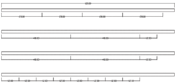
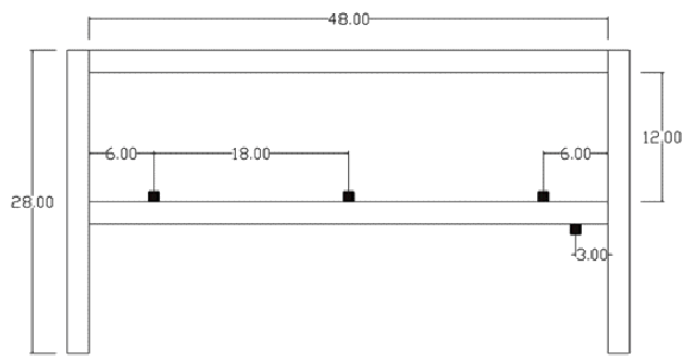
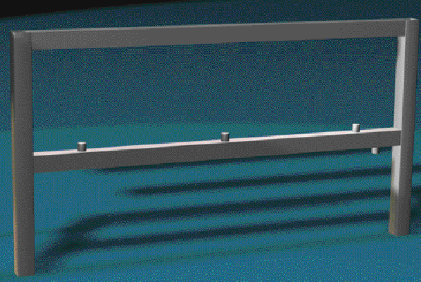
You will need to cut four each 48” rails, four each 28” legs and ten each 12” cross beams. These can all be cut from the two 20-foot 2” X 2” X 0.120” stainless tubes — or better yet, have your local steel yard cut these beams exactly in half; it is much easier getting four 10’ sticks to your shop than two 20’. Save all the scrap from cutting. You will need these stainless droppings to learn how to weld, and for the control panel and the pump mount at the end of the project.
Drilling the Holes
There are many wire chase holes inside the joints in this project as all of the wiring runs inside the tubing. These holes allow the wiring to run down the rails, up the legs, across the cross beams, etc. This is not a necessity, but makes for a very clean wiring installation with the wiring hidden in the lower front rail. Remember NO wiring can run through the gas beam or the upper surface as it gets VERY hot! Unless you are using an automated gas system, employing the ASCO valves and LOVE switches, you may not need wiring chase holes at the joints and exit holes at various locations. Simply affix all wiring to the outside of the tubes.
The factors that matter in drilling stainless by hand or any other method are time, pressure, control, lubricant, time and, of course . . . a Unibit step drill! In any case as we know, it is a very slow methodical forearm pain, but purchasing an ingenious little Unibit will be the best investment you can make for your arms. For my application, there are a lot of 3⁄4” holes to drill as well as 1⁄2” holes for the switches in the control panel. I made short work of this by using the Unibit, or “step” bit as they are also called. These are easy to find, and invaluable in any project of this size that has 17 holes drilled by hand in 1⁄8” stainless. The trick to saving energy and saving your Unibit is to use a quality stainless cutting oil. Let the tool do its job while you save your back and elbow.
Let’s Weld!


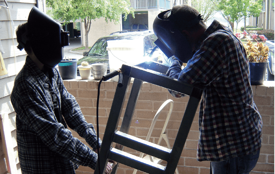 After cutting your steel, it is time to find a VERY level place to perform your welding. Keeping everything level is the key to any great project. Remember that each cut should be as dead square as you can possibly keep it, free of burrs, oil, chips and such. Any deformities will show through in your welding as a flaw, and in general, you will be working with this tubing for quite a while. It is best to keep things very clean. Enjoy the cleaning process, and have a homebrew handy!
I am assuming you will be welding the frame yourself; nothing is more rewarding. I learned how to MIG weld using my new Hobart 180 and a few Brutus cuttings before the task of putting real wire to metal even began. I studied great Internet boards like hobartwelders.com/mboard/ beforehand. I read everything I could just like I did when it was my very first all-grain brew day. By following the simple instructions on the welder door itself, it was nothing at all to lay down a great weld with a small amount of time, patience and practice. I would say that if you wanted to tackle the task of welding up your own rig then go for it; it is a most rewarding combination of learning a new craft, and then reaping the brewing rewards. The new welders today are much lower in amperage. Most all the hobby Metal Inert Gas (MIG) welders can easily and safely run on house current as they are meant to do. It did cost much more to purchase a good welding unit, especially one that would tackle this 1⁄8” stainless tubing. I also purchased several other items required to weld stainless. A gas bottle of 100% argon and regulator, a welding hood (actually two, one for my helper as well), gloves for everyone, plenty of 308 welding wire, spare tips and so on. All the welding items needed will become very apparent with a little knowledge of the welding process.
With the exception of the gas beam that you will fully weld and pressure test up front, you are going to tack weld this entire frame together (see page 7). Tack welds are very easy to remove, if necessary, with a grinder. You can also move things around with a rubber mallet to get things square as tack welds are very small welds intended simply to barely hold things together. I would concentrate on keeping everything square up front on this project, and keep your angle grinder very handy! You will need a good framing square, plenty of clamps, or in my case, I used the little 1” ratchet straps that you can buy at any Wally World. Clamp and tack weld as necessary. Once the frame is strong enough to stand up on its own, stand it up! Keep everything VERY square and then re-square again if necessary. If need be, the ratchet straps are great for helping to keep a square day with Brutus. You can strap two opposing legs at a diagonal and ratchet the frame into position. Once the frame is standing on its own free will, you can apply more small tacks as you see fit. Make the whole frame square and make the whole frame strong before final weld-out. Welding is funny that way. Welding moves metal. It moves a lot. This is where good strong tack welding and the ratchet straps come in handy. As with any good project, the final product will only be as good as the hard work up front.
Full Weld-out
Weld the frame fully only when all of your up-front preparations are complete. You should have the gas beam fully welded and everything else completely and strongly tacked in place, keeping everything square. Weld every joint 100%. I started at the face of the frame and welded all the front joints. Then I flipped it over and started again on the back. I went back and forth, top to bottom, side to side until every joint was complete. The idea is to not let any one area of the frame to get too much heat at one time. This is where metal moves. If you start at one end and systematically move to the other, the frame will be impossible to keep square in the end. Hot metal will move that much due to the very heat of the welding process itself. After welding, I elected to grind flush the welds on the top of the frame. I didn’t want to drag my nice brewing pots over these welds and scratch the bottoms. I also decided to grind flush the welds on the front of the frame as well to look great. I used an angle grinder with 40 grit paper to knock them down first, then I polished them off with a little air powered angle grinder and some 80 grit sanding wheels. After the whole weld job was complete, I took an orbital sander to the whole frame with some 120 grit sand paper. This gave the whole frame a very professional and finished look. With all the welding complete, it is time to turn to other tasks.
The Pumps
The pumps are mounted directly to the frame by way of drilling and taping the holes, and bolting the pumps in place. As with all single-tier systems, fluid dynamics make brewing possible without all the heavy lifting, and a well laid out fluid scheme can make a great brew day in any case. Brutus has a lot going for it in this regard; two March pumps are no exception to the rule. Each pump is controlled with its own master power switch at the control panel, and is operated manually. Coupling these with the high temperature silicone hoses, quick disconnects at every possible location, and you will never return to vinyl!
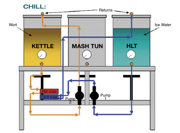
The real art I think are the returns that are affixed to the lids instead of welded fittings at the top edge of each pot. Fittings at the top edge of each pot require hose changes in the midst of high temperature brewing. Having all the returns in the lids only requires moving the lids about from pot to pot. These bulkhead fittings are most simple to install into the lids and are widely available.
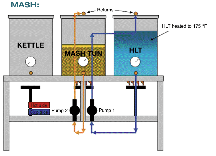
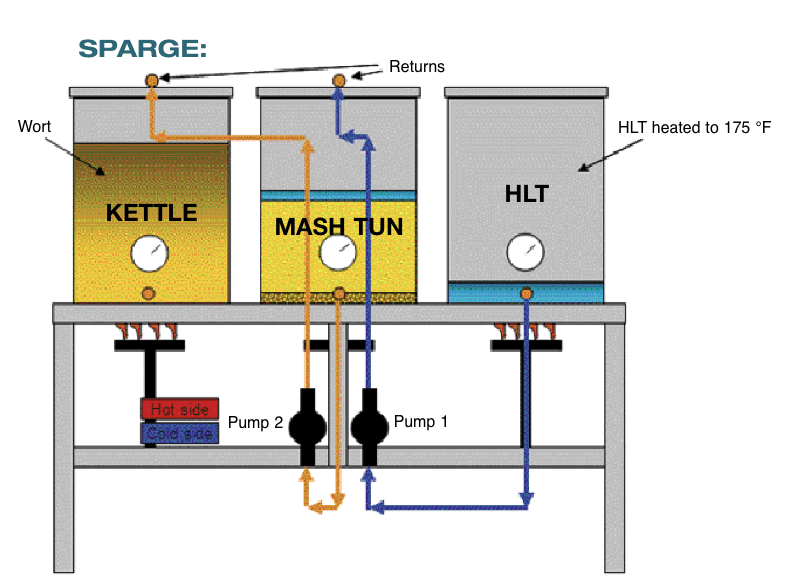
For the return tubes themselves, a curved piece of copper is affixed to these bulkhead fittings, and when the lid is installed onto the pot, the copper tube is actually touching the inside side of the pot. These tubes are simply a means to return the scorching wort, the freezing chill water or sparge water to their respective pots. These returns can be used to set up a whirlpool in the kettle, sparge as I do or return the hot wort to the kettle as I do during the sparge. (See pages 10 and 11 for a summary of my brewday procedures.)

Electrical
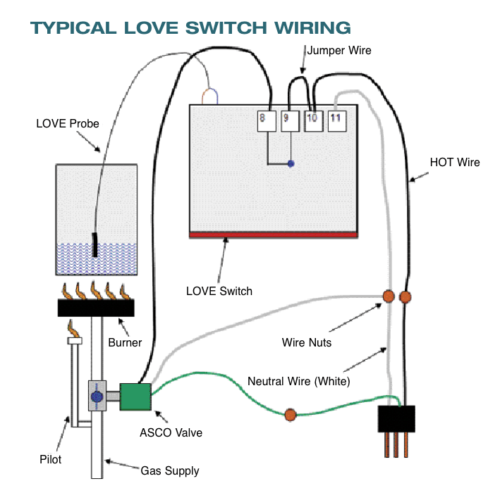


Electrification! You know really way down inside, we all want to plug something in. There are six electrified elements on Brutus. Basically the control panel is made up of two control sections: Mash section (middle pot) and the HLT section (right pot); each is wired from a main power bus. There is one ASCO gas valve, a LOVE temperature switch and a March pump for each half of the control panel. It takes two of everything to keep things moving from the sparge to the mash, from the mash to the kettle, cooling, whirlpooling, etc. Wiring Brutus was relatively easy as everything is basically a simple switch allowing one component to turn on and power up another; a master switch at each device ensures a systematic brew day. Though the temperature of the sparge water and the mash are fully controlled by the LOVE set points, the pumps themselves and the kettle burner are fully manual. As
with any electrified brewing gadget, safety is in order. Always power up through a GFCI outlet. Another safety note: as built, the wiring is exposed under the panel. Enclosing the electronics in a NEMA 12 enclosure guards against direct contact and liquid splashes.

Fire!
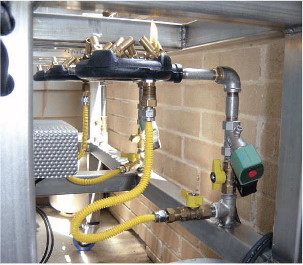
The three 100,000 BTU low pressure burners are fed by way of what I like to call a gas beam. This gas beam is the lower rear support and has to be welded air-tight to be safe to use. Stainless fittings are welded to this beam and from these fittings; the low pressure burners are attached. This gas beam is really nothing more than a fancy gas pipe! The gas beam is pressurized from the tank to only 0.4 PSI by way of a low pressure regulator from MoreBeer! This is required when using the low pressure burners like this system employs. This beam has three 1⁄2” NPT Full couplings welded onto the top of its centerline and one 1⁄2” NPT Full coupling on the bottom. These couplings have the gas plumbing attached to it and support the burners. The bottom (fourth) coupling is the throughput from the low pressure regulator attached to the propane tank. I found it very important to weld the gas beam fully at this point so I could be assured that I would have no leaks in the end. It is also important to pressure test this beam at 1 or 2 PSI using your Argon, or CO2 from your bar and soap it up good. It is critical every leak be repaired at this stage for your safety. A simpler alternative to this gas beam is to use tubing and compression fittings running behind the beam to deliver gas.
Chilling
When the time comes to chill out, I wanted an all-in-one unit, small and something that would knock down this Texas heat. I wanted a mountable unit, gorgeous looks and something that I didn’t have to pick up and put in my wort. Again, I wanted an all-in-one brewery. The Therminator — a plate chiller — fits the bill perfectly and sits cozy in its little nook.
As with any Texas rig, ice is your friend. I have a great method for the chill using the HLT as an ice chilling tank recirculating the chill water through the cold site of the Therminator and back to the HLT, while recirculating the hot wort through the hot side and back to the kettle! Want to knock a batch back to the Arctic, this method works like a charm!
Test Run and Brewday!
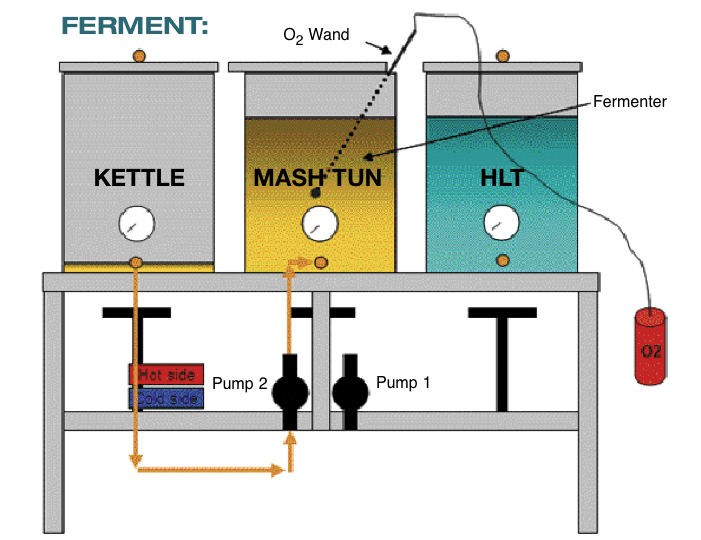
Nothing will be more peaceful than the day you put flame to Brutus. A first dry-run will only prove that it is already brew-worthy, and you should have brewed real beer instead of a mock water-run! My wife Moonbeam and I have brewed some 50-odd batches to date on Brutus, and with each batch, I am already planning the next! It is still a pleasure to brew even though some elements of an otherwise busy brew day are taken over by automation. I think the tasks that remain are really the tasks that make my brew day enjoyable, and leave me feeling really in control of my medal wall! The diagrams on the last two pages of this article show how I use Brutus, although you of course will develop your own procedures for your own rig. My website, www.alenuts.com, has more more pictures of the build, and photos of Brutus in action. If you build a Brutus of your own, send BYO a picture!
Using Brutus: Hot Side
Using Brutus: Cold Side
