Build a Beer Engine
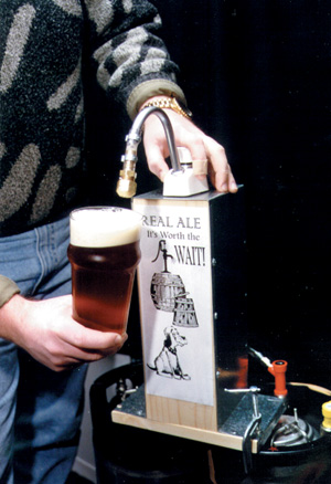
A group of beer aficionados and their significant others gathered recently to test drive the sleek design of the newly released Fogarty Homebrew Home-Built Beer Engine for the 1997 model year. Only one prototype has been built, but the design is so elegant and oh so sexy that predictions are flying that a fleet of these babies will soon be taking to the homebrew highways of America en masse.
Well, that might be overstating it a bit. Except the part about sleek, elegant, and sexy. It was all those things and more, pulling pint after perfect pint, each softly bubbly with a thick creamy head, smooth as silk and tasting like more.
Even the test drivers who normally avoid the barley brew were going back for seconds, thirds…sixths. Admittedly, part of the draw was the pump itself, it worked so well and so effortlessly. But part of the attraction, we are convinced, was the excellent character of the naturally conditioned beer.
If you love authentic, hand-pulled English ale, read on. For less than $50, you will be able to build an engine to accent your homebrew shack and make a real difference the next time you tap a keg.
If you are still bottling your homebrew, well, you should seriously consider getting into kegging just so you can experience the joy of the Fogarty Engine.
The Players
It started with a simple assignment. Build a beer engine. Why not? We had the technology. We had the Yankee ingenuity. And we had John Fogarty.
Fogarty owns What’s Brewing, a homebrew supply shop near Atlantic City, N.J. He is known to be able to build anything, for any purpose, with his bare hands. He’s one of those guys we all envy. He can bend stainless in perfect creases. He knows how to countersink. He knows about pipes and wires. He can weld.
Plus he’s an accomplished brewer who understands beer. He possesses the beer passion of Charlie Papazian crossed with the dexterity and mechanical skill of Norm Abrams, with a hint of Tim Allen thrown in for enthusiasm. He’s a marvel of modern science.
With this guy on our team, we were on our way to a beer engine that worked. This was never in doubt.
Of course, as is his wont, Fogarty outdid himself. The thing worked like a charm. Like it was born to pump English Ale. Well, come to think of it, it was.
The Pump
Fogarty’s first inspiration was the paint stick. The paint stick is one of those infomercial products that has now burst the seams of the As-Seen-On-TV warehouse and spilled onto the shelves of most big paint and hardware stores. It is a big pump that looks like a broomstick, with a paint roller stuck on one end. You fill the handle with paint, then pump it into the roller and — theoretically — apply it to your ceiling and walls.
Fogarty tinkered with turning the paint stick into a beer engine and apparently got it to the prototype stage. But he killed the idea after building it and went on to bigger and better schemes.
“I was worried about the plastic components and joint material in the paint stick. I’m sure it’s not food rated. Plus the thing’s kind of big and ungainly. I wanted something smaller and more compact,” he says.

Putting his Tim Allen hardware sixth sense into high gear, he started stalking retail outlets, looking in camping and boating accessory aisles. “I had a hunch I would find some kind of suitable pump in accessories for the great outdoors,” he says. The trail got hottest when he looked at boating parts and he ended up in a marine-supply specialty shop.
He recalls the moment of success, which was preceded by several minutes of confusion.
“I asked the young lady behind the counter if she had pumps. She took me to electric pumps, the kind you use to pump out the bilge water. ‘No, I was looking for a hand pump,’ I said. She took me to the hand-actuated bilge pumps. ‘No, I’m looking for something to pump clean water,’ I said.
“That’s when I struck pay dirt and she took me to the galley pumps. ‘Is this for your boat?’ she asked. ‘No, for my bar,’ I replied. ‘For water?’ she asked. ‘No, for beer,’ I replied. The conversation pretty much ended there. She was in way over her head,” Fogarty says.
Fogarty had found the object of his search. A Whitestar Products Fynspray Galley Pump made in New Zealand.
“I checked it out pretty well. It was all food-grade plastic, stainless, and brass,” Fogarty says. “I made sure it contained no copper. Water and copper you can get away with. But copper and beer don’t mix.” Copper can oxidize beer flavors.
The pump passed muster. The rest of his task was to fit it so it would connect to a Cornelius soda keg and to build a housing that could be mounted so the pump could be worked with one hand.
Soon, the Fogarty Engine took shape.
Fogarty added a sparkler head on the outflow to generate that classic creamy English beer head and made a few trial runs with plain water. There seemed no reason to expect the thing wouldn’t pull ale.
The Beer
And pull ale it did.
The ale used to put it through its paces was a keg-conditioned extra special bitter/India pale ale with about two weeks of cellar time on the meter.
The engine was sublime, and so was the ale. It pumped effortlessly. A feather-light touch was all that was needed to work its smooth, stainless-clad action. An unexpected bonus was the fact that the Whitestar pump works in both directions. Whether you push or pull the pump handle, beer keeps flowing into the pint.
This made things go very quickly, too. In true English fashion the beer was not overly carbonated. It had been primed with one-third cup corn sugar, and the keg was left vented for 12 hours before the pump test. This, combined with the engine’s super-efficiency, made pulling a pint a simple, quick task. It literally took no more time than pouring a pint from the CO2-dispensed keg, sitting alongside for taste test and dispensing comparison.
The pump dripped slightly immediately after pulling pints but stopped in short order. To avoid a mess you need to consider this when installing the engine in your home brewery.
If you’re a true real-ale homebrewer, spend your next day off building yourself a Fogarty engine.
But be careful. The world will beat a path to your door if word gets out.
Fogarty Beer Engine Parts
The beer engine is actually a pump braced inside a box. The box has a wooden front, back, and base. The sides and top are made from a single, thin sheet of aluminum, bent 90 degrees at four points to resemble an upside down U with wings or dog ears.
Frame Parts:
• Aluminum sheet 40 1/2 inches by 5 inches
• Two pieces 3/4-inch pine, 4 1/2 by 14 inches for front and rear plate
• Wood for base plate. The size varies, depending on your needs. A base plate is made to be mounted or clamped to a steady surface or made heavy enough to keep the engine immobile during use.
• Wood screws
Pump Parts:
• Whitestar Fynspray marine galley pump
• 1/2-inch inner-diameter (ID) plastic tubing, 2 1/2 inches long
• 1/2-inch barb by 1/4-inch barb reducer, stainless steel
• 1/4-inch beverage tubing, 5 feet or as much as needed
• Two 7/8-inch stainless steel hose clamps
• One 1/2-inch stainless steel hose clamp
• One 1/4-inch barb by 1/4-inch female flare in stainless
• Soda connection
• One 1/4-inch male flare
• 3/8-inch tubing, 2-inch length
• 3/8-inch barb by 1/2-inch male pipe thread in brass
• 1/2-inch male-pipe-thread cap with blunt end (drilled, as sparkler)
• Two #145 crimp clamps or stainless steel hose clamps
• Teflon tape
Putting it Together
The Aluminum U-Bracket:
The aluminum bracket is created by bending a straight sheet of aluminum into a U-shape with dog ears. The front and back wood pieces are screwed to the bracket through holes that you drill before bending the sheet. The dog ears are screwed to the base. Note: The aluminum bracket is not an absolute necessity. You could build the entire pump cabinet of wood alone. Use your best judgment.
1. First put a cloth or some type of rubber material down to prevent scratches and marks on your finished material. Lay the 40 1/2-inches-long-by-five-inches-wide aluminum strip finished side (the side you want visible on the finished product) down. Find and mark the center point of the length of the aluminum strip.
2. From the center point measure 2 1/4 inches out and mark or score a line across the material. Remember to mark the back side of the material. Do this again in the opposite direction. These are two of the places where you will bend the material. Also mark the strip four inches in from the ends.
3. Now that you have marked your lines, you need to mark for drill holes. The first hole is on the centerpoint line 2 1/4 inches up from the front edge. This hole size is 1 1/4 inches. Through this hole you will fit the shaft of the pumping mechanism.
4. The rest of the holes are one-quarter inch in diameter and are for mounting and assembling the face, rear, and bottom panel. Along the lengths of the two sides (the 40 1/4-inch length), the holes should be drilled three-eighths of an inch from each edge. For the hole placement, the distances from the center point line working out to the end of the strip would be 5 1/4 inches, 8 1/4 inches, 11 1/4 inches, 14 1/4 inches, 17 1/2 inches, and one-half inch from the end. Repeat this in the other direction. You now should have holes down both sides from end to end.

5. At this point you will need to bend the aluminum material. Clamp the material with a C-clamp and a flat piece of steel or wood. A metal brake or bending tool would be a great asset for this type of work.
Clamp the steel or wood down with the edge of the material being clamped on the line marked or scored on the metal 2 1/4 inches away from center. Make sure to clamp the steel or wood on the center-side of the mark.
6. Bend the material to the 90-degree position, which would be back toward the center mark, exposing the finished side. Repeat this step on the other side of the strip. The finished product should now look like a U.
7. Now at the lines four inches from the ends, you need to bend the metal away from the center point. Make sure you clamp the steel or wood on the center-side of the lines four inches from the ends on the finished side of the material. You will now bend the metal toward the outside of the U. This will look like a tee when both sides are complete or like dog ears.
The Wood Stock:
You can now cut your wood. The pieces are 4 1/4 inches wide by 14 inches long. The rear piece for the engine should have a three-quarter-inch notch taken from it at the bottom and in the center. This will be needed to allow the beverage tubing to exit the case and attach to the keg.
Finish the wood prior to assembly. Stain, paint, or hand rub with oil.
A quick test for fit is a good idea. The base plate can be as large as needed. This will truly depend on how you will mount and dispense your product and the portability you desire from your engine.
Holes for the Sparkler Head:
The half-inch male-pipe-thread cap should have a half-inch blunt end in the shape of a circle. Within this circle you need to drill holes so the beer will come out.
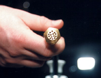
We used a number 52 drill bit, a very small diameter. The pattern for the 14 holes is in four rows. The top and bottom rows have three holes each, the center two rows have four holes each. The rows of three holes are staggered from the holes in the two rows of four. This seems to allow a nice spray pattern.
The metal cap is brass and does not need much pressure from the drill bit to penetrate and pierce through the cap. Use caution, as it is easy to break a drill bit of this diameter. Some finesse is needed if you are going to do this with a hand-held drill. A drill press makes this step a little easier.
Assembling Your Engine
Now that all the manufacturing is done, it’s time to assemble the engine.
1. Insert the galley pump through the 1 1/4-inch hole in the metal housing. This will be a tight fit, so be careful not to damage the threads when passing the pump through the hole. The pump may have to be screwed through in order to fit.
2. Use the plastic nut that comes with the pump assembly and tighten the unit to the metal U-frame. You want the front of the pump to face the side closest to the front edge of the housing. On the top of the unit, the pump should be about a half-inch from the metal frame.
3. Connect your 2 1/2 inches long by one-half inch ID tubing to the barb at the bottom of the galley pump. Use the seven-eighths-inch stainless steel hose clamp to secure it.
4. Now place another clamp on the hose and insert your half-inch barbed by quarter-inch barbed stainless steel reducing coupler. Again use the clamp to secure the hose to the coupler. Now get your length of quarter-inch beverage tubing. Attach the hose to the coupler and secure with the half-inch hose clamp.
The other end of the tubing will be connected to your keg. Put on a crimp clamp or hose clamp on the end and insert the stainless steel quarter-inch barb by quarter-inch female flare nut and secure. Attach your soda-keg connector.
Note: You do not need the stainless steel quarter-inch barb by quarter-inch female flare if the soda-type connector you are using is barbed. However, the ease of maintenance and flexibility of quarter-inch male-flare-type soda connectors is highly desirable.
The hose assembly is now complete.
5. Next, connect the brass three-eighths-inch barb by one-half-inch male pipe thread to the half-inch male-pipe-thread cap. The cap needs to be drilled prior to assembly. We recommend using Teflon tape on the threads when the pieces are screwed together.
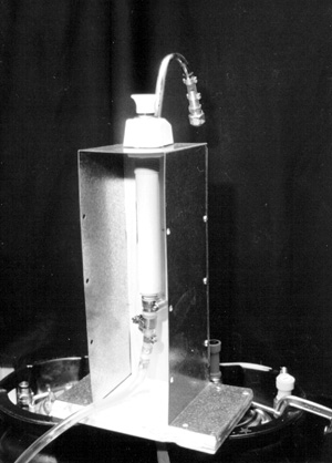
6. Attach the three-eighths-inch tubing onto the goose neck of the pump faucet. Secure with crimp clamp or hose clamp. Place the other clamp on the other end of the tubing and insert the brass hose barb into the tubing. Secure with crimp clamp and/or hose clamp. The crimp clamp gives a cleaner finish. Functionally, either type of clamp is the same.
With the pump secure inside the aluminum U-frame, you can now attach the front, back, and base of the assembly with wood screws.
When it comes to using your handpump, attach it to the keg.
These are the basic instructions for assembly. Adjustments, adaptability, and creative modification are all within the realm of the builder. The builder’s needs and style of display and dispense should be considered prior to start of construction.
The Side-by-Side Test Drive
To test the performance of the Fogarty Beer Engine and to compare the differences in flavor between naturally conditioned and force-carbonated beer, we brewed a double batch (10 gallons) of ESB/IPA, cask conditioning one half and chill-and-shake carbonating the other.
“Engine” Special Bitter, aka India “Pump” Ale Recipe
(10 gallons, extract and grains)
Ingredients:
• 6 lbs. pale malt
• 1 lb. British Crystal, 60° Lovibond
• 10 lbs. light extract syrup
• 1 lb. demerara sugar
• 3 oz. Northern brewer hop pellets (7% alpha acid), for 90 min.
• 2 oz. Fuggle hop pellets (4.5% alpha acid), for 30 min.
• 1 oz. Kent Goldings pellets (4% alpha acid), for 15 min.
• 1 tbsp. Irish moss, for 15 minutes
• 1 pint starter of Wyeast London Ale Yeast
Step by Step:
Mash grains in 2 1/2 gals. water at 155° F for one hour. Sparge to 11 gals., bring to a boil, remove from heat, and add extract and demerara sugar. When boil resumes, add Northern brewer hops. Boil 60 minutes and add Fuggle hops. Boil 15 more minutes and add Kent Goldings and Irish moss. Boil 15 more minutes. Cool, and pitch yeast. Ferment in primary for 10 days at 60° F.
OG = 1.050 FG = 1.010
Special Instructions:
Both kegs were fined with gelatin.
We tried to treat both kegs the same in terms of temperature. The cask-conditioned keg was primed using 1/3 cup corn sugar, boiled in 1 cup water. Then both kegs were laid on their sides and kept at 55° F for five days.
Three days before tasting, we stood the kegs up and refrigerated them. The CO2 keg was carbonated to 2.2 volumes of CO2.
Tasting Notes:
On tasting night we fixed the Fogarty engine to the cask-conditioned keg. The other keg was tapped traditionally, with CO2.
The beer was very hoppy. In fact we overshot our bitterness level slightly. Utilization was greater than usual because of the greater volume of boiling wort — the recipe was for 10 gallons.
This mistake, however, benefited the experiment. The extra bitterness made the differences between the kegs readily apparent.
The hand-pulled ale was creamier and smoother than the CO2-dispensed version. The sparkler on the engine created a very pleasant, dense head that contributed to the very distinct creaminess of the overall beer.
The main difference between the two was the sharpness of the hops. In the force-carbonated beer, the hop bitterness was very assertive, not only at the first sip but throughout the entire glass. This is due in part, we suspect, to the fact that the flavor of dissolved CO2 is bitter on its own. Similar to the flavor of plain seltzer water.
The hop sharpness was significantly subdued in the naturally conditioned version.
Bottom line, they were very different.
Some of our tasters preferred the CO2 version. Predictably, these were the hopheads among us. However, the hand-pulled ale was preferred by most of the tasters, including a few who professed to “not like beer!”
Brewing Notes:
The level of bittering hops should be reduced in future batches.


