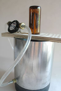
Build a Better Bottle Capper
One thing I really like about the homebrewing hobby is that it allows me to build various gadgets and equipment that I can use in my basement brewery. I am constantly thinking of ideas that will either make a process easier or at least make it more enjoyable. Recently I came up with a project that does both: A pneumatic bottle capper.
I came up with the idea one day after I came across a spare air cylinder. Immediately the idea of a pneumatically-powered capper came to mind. One of the first things I wanted to figure out was how to attach a capping bell to the end of the cylinder rod. So I brought my newly-discovered air cylinder home, located my bench capper and unscrewed the capping bell off of it. To my surprise, the threads were an exact match!
The next step was figuring out if the force generated by the air cylinder would be enough (but not too much) to do its job properly. To calculate the force output of the cylinder, I first figured out the area of the piston. The cylinder has a 2-inch (5-cm) bore which means the piston area equals pi x (1)2 or 3.14in2. The force is then calculated by simply multiplying the piston area by the PSI of the compressed air. So at 100 PSI, the cylinder will exert 3.14in2 x 100 PSI, or 314 lbs. of force. This seemed like a lot to me until I compared it to my bench capper. The lever on that is 10 inches (~25 cm) long, and the distance from the pivot point to the capping point is 1.25 inches (3 cm). This means that the force exerted at the capping point is eight times greater than the force applied at the end of the handle (10/1.25 = 8). So, figuring backwards, in order to get a 314-lb. force at the capping point you would need to apply 39.3 lbs. at the handle (314/8=39.3).
I wanted a frame design that was simple, yet robust. The concept involved using a section of 2-inch (5-cm) square steel tubing sandwiched between two 1⁄2-inch thick by 21⁄2-inch wide (1.25- by 6.25-cm) steel plates. I mounted the cylinder to the frame by using the appropriately sized hex nut welded onto the top plate. I thought this would be much easier than drilling and tapping such a large threaded hole into the steel plate. I based the height of the frame on a standard 9-inch (23-cm) tall longneck bottle, making sure that the cylinder would be somewhere near the end of its stroke (but not at it) when capping, allowing for plenty of room to load and unload bottles when the cylinder was retracted. Of course, this means that I would have to make adjustments if I were to use bottles of any other height.
Once I had a frame design, I cut the steel bars and tubing, drilled the necessary holes and welded the parts together securely. After the weldment was thoroughly prepped and cleaned, I primed and painted it. Once the paint was dry, I screwed in the four rubber leveling feet, installed the air cylinder, and screwed on the capping bell.
Looking at the finished capper frame I noticed that I needed a way to locate each bottle in its proper location, so I made up a guide by drilling a large hole in a thin piece of clear plastic. I cut it to size and adhered it to the base of the frame using double-sided transfer tape.
To initiate the cylinder’s actuation, I used a foot-operated pneumatic valve. I routed the air tubing through the frame, then connected the tubing to the fittings on the air cylinder and foot pedal valve.
Safety Tips:
• Wearing safety glasses is recommended due to the potential of a bottle breaking if the bottle is not lined up correctly or the capper is not operating as designed.
• You can attach a clear plexiglass shield in front of where the bottle rests so, in case a bottle breaks, there is a barrier between you and the glass.
• Never put your hand between the capping bell and the top of the bottle. Put the bottle cap on top of the bottle before placing the bottle below the
capping bell.


