Build a Hop Drying Oast

Concept overview
What we’re building is a dehydrator that uses active convection (driven by a small fan) as the main means of dehydration. The hops are suspended on a drying rack and the fan pulls a constant flow of air over the hops, which carries the moisture away.
The following build guide is just one of many ways to put together your own oast. The size, shape, look, and general construction of the oast can be almost anything you want to match your needs (or whatever you can manage to bang together, as in my case). What is critical to the design is that there is an adequate flow of air across the hops. Everything else is negotiable.
Tools and materials
A miter box and back saw, hand saw, keyhole saw and sanding block, along with a power drill and a staple gun will suffice for this project. If you have power tool equivalents to these hand tools, use them at your discretion.
I built my oast primarily from 1⁄2” medium-density fiberboard because it is an easy material to cut, it takes glue very well, and it is economical. I used inexpensive 1 1⁄2” by 3⁄4” pine stock to make the drying rack frame and the interior rack supports. (Note: These are great materials for prototyping and proof-of-concept builds, but if I had to do it over I would’ve gone with a thicker, higher-grade plywood for the box and some hardwood stock for the rack). I used vinyl-coated fiberglass screen to finish the drying rack but you could also use stainless steel screen.
I used two small utility hinges to create a “front door” for the oast. And to keep the door closed, I used a sash lock commonly used to latch windows. You can also add a knob- or bar-style drawer pull to complete the door paradigm. I used a medium-duty staple gun to attach the screen to the drying rack. Look for a gun that uses T50-sized staples. I don’t recommend using staples smaller or thinner than the T50.
Electronic components

To generate the convection current, I used a 65-mm (2.5”) 12 Volt DC fan. This is the type commonly found inside computers to help keep the processor cool. They move a lot of air (about 25 cubic feet per minute) and have a low current draw (about 0.125 amps). A fan like this will “turn over” the entire interior air volume of the oast two or three times per minute. You can scavenge one from an old PC or you can buy one new from big-box consumer electronics stores or Radio Shack. But you don’t need to use a 2.5” fan specifically. The most common size you’re likely to find at a store or in a computer is 80 mm (3.125”), which will also work.
Traditional oast designs require a heat source, although from what I’ve read about DIY dehydrating, heat is not a necessary component. This design does not use heat, however, a very simple and relatively safe way to go about it would be to position a typical electric space heater a few feet away from the air vents that are drilled into the bottom of the oast. The fan on top would pull the warm air through the bottom holes and out the top.
I also added two simple controls to the fan: an on/off power switch and a variable fan-speed control. The power switch I used is a simple “pushbutton” SPST (single-pole, single-throw) switch. Any style of SPST switch will work, whether it’s a toggle, pushbutton, slide, rocker, etc. Avoid “momentary” type switches, which will only allow current to the fan while you hold the button down.
The speed control is a 500-ohm linear potentiometer, which, along with the SPST switches mentioned above, is available at most Radio Shack stores. If you can’t find a 500-ohm potentiometer, you can use higher values, such as 1k-ohms or 2.5k-ohms. Higher values than this will work, but as you go higher, the useful range of the potentiometer decreases and the touch sensitivity of the control increases until it is almost like an on/off switch.
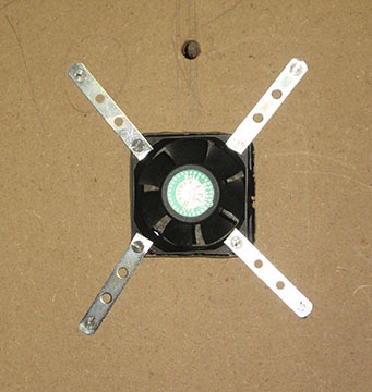
To fasten the fan to the top of the oast, I used #6-32 machine screws (along with the corresponding washers and nuts) and four flat pre-drilled brackets.
Additionally, you’ll need a DC power supply to run the fan. Just about any DC supply will work, from 5 volts up to 12 volts. You probably have a few of them laying around your house left over from electronic gadgets you no longer use or own. What you’re looking for is the typical black, square adapter that plugs into a wall socket and has a round adapter plug with a metal or plastic/metal tip. Just cut off the plug end and strip back the plastic insulation about half an inch to expose the wires. Use a voltmeter to verify wire polarity (i.e.: which wire is ground). Check your fan for current requirements, which will be specified on the fan case. Be sure that your power supply can deliver the specified current (usually between 0.1 and 0.2 amps).
Dimensions and structural design

Because it was easier for me to visualize in my head, I built my oast as a cube (my wife affectionately calls it the “big box ‘o hops”). Each side is roughly 24” (61 cm) because the fiberboard I bought came in 48” x 24” sheets, so going with that size saved me a few cuts at the beginning. You can build yours in any size or shape that fits your brewing space. So long as the air is flowing inside, the shape of your oast is irrelevant. Following is a general guide you can follow to build your own DIY hop dryer. There are many ways to get the job done, and this is just one of them. Feel free to deviate from the process below at your discretion.
General build guide
Assuming you want to go with a box-like shape, you’ll need to cut six sections of fiberboard or plywood. The dimensions of each section will vary based on your design and also based on how you intend to join the sections together. For simplicity, I chose to use common butt joints, but I reinforced each joint with dowels for added strength. You could opt for any style of joinery that you’re comfortable with (miter joints or rabbet joints would work exceptionally well here, as would butt joints reinforced with biscuits).
I opted to join the sides and rear sections with the bottom section first, and left attaching the top and front for the last part of the build. Before gluing, drill a few 1⁄2” holes near the bottom of the left, right, and rear sections of the box. These holes serve as intake vents from which the fan can pull air up through the oast. Also drill a 1⁄4” hole at the top of the back section for the power supply wires.
Now apply glue to the sections, fit and clamp them, and wait for the glue to dry. With most wood glue, the joints will set up enough to remove the clamps after about 30 to 45 minutes, but I would advise that you take your time and let the glue fully cure (which takes about 24 hours) before taking the clamps off. Better safe than sorry.
With the bottom and sides clamped and drying, now is a good time to mount and wire the fan and electronic controls to the top section of the soon-to-be oast. Lay the fan flat on the board where you want to mount it (I recommend close to the center for more even airflow) and trace the outline with a pencil or pen.
For my oast, I decided to mount my fan flush with the board, but you can also mount it directly on top of the board. This is much easier than flush mounting, and the overall performance is practically identical.
For flush mounting, cut around the fan outline you traced on the board. You can use a rotary tool (Dremel, RotoZip, etc), jigsaw, or keyhole saw to cut the hole. The fan should just fit inside the hole. To secure the fan, use eight #6-32 machine screws with washers and nuts along with four flat brackets. I made brackets from #4 mirror hanging eyes.
For top mounting, come in about a 1⁄4 of a inch from each side of the fan trace and cut the hole. Use four of the #6-32 machines screws, washers, and nuts to secure the fan.
Once your fan is mounted, choose a spot for the controls, drill a 5⁄16” hole for the potentiometer shaft to fit through, and also drill a hole for the power switch (the size of which will depend on the switch you choose). I recommend positioning the controls near the fan, as this makes for a cleaner, shorter wiring run.

Most potentiometers and switches were not designed to be mounted to materials thicker than about a 1⁄4 of an inch, so you’ll need to glue them in place. An all-purpose adhesive like Gorilla Glue is ideal, but I found that craft-grade high-temperature hot glue works admirably.
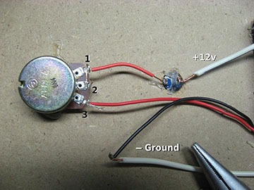
Connect the positive wire from the power supply to one of the lugs on the SPST switch (it doesn’t matter which one), and use a short piece of shielded wire to connect the other lug on the switch to lug 3 of the potentiometer. Connect lugs 2 and 3 of potentiometer to each other. Connect the red (positive) wire from the fan to lug 1 of the potentiometer. Finally, connect the black (ground) wire from the fan to the ground wire of the power supply. The complete wiring, left unsoldered for clarity, is shown in Figure 4. I recommend soldering all connections — except for the ground wires which can be spliced together with a small wire cap connector — but it’s not 100% required.
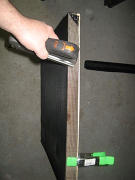
Now that the wiring is finished, and the glue is *still* curing, let’s move on to the hop-drying rack. Cut four pieces of wood stock for the rack’s frame. The lengths for these should be about a 1⁄4-shorter than the interior width of your oast, and at least an inch shorter in depth, but this will vary some depending on how you join them. As with the oast box itself, I used butt joints to join the rack and reinforced the joints with staples. Corner clamps make this job very easy, but they aren’t required (Figure 5). When the glue is dry, cut a piece of vinyl screening about an inch wider on each side than the frame itself. Staple the screen to the frame along the side edges (Figure 6), and also add a row of staples along the bottom side edges. Make as many racks as you need for your hop harvest.
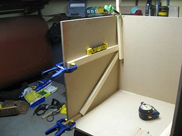
By now, the glue securing the oast joints will be dry, so you can add the interior supports that the rack will sit on. I’d suggest using at least 1⁄2” (0.23 cm) thick stock for these. Cut two pieces (per rack) about 2” (5 cm) shorter than the interior depth of your oast. I glued the supports to the oast using clamps and scrap stock to secure it and used a bubble level to get it even (Figure 7).
When the rack supports are cured and dry, glue the top section to the rest of the oast (Figure 8). Now all that remains is to attach the front section to the oast with hinges. I chose to have the front open forward like an oven, but you could also have it open from the side like a cabinet or refrigerator. I chose to have the front open forward like an oven, but you could also have it open from the side like a cabinet or refrigerator. To keep the door closed, you’ll need some type of latching mechanism. I used a window-style sash lock.

