Build a Better Grain Mill
I like starting my brew days by milling my own malt. My first mill was a hand-cranked model and the first thing I did upon receiving it was install my electric drill to power it. Since the drill chuck diameter was larger than the distance from the shaft to the base, it was tough to install tightly and the chuck rubbed on the provided MDF base. It wasn’t a great solution and was a pain to keep the speed consistent. My next attempt at a power solution was repurposing an old electric mixer motor, but it didn’t have enough torque to maintain rotation. My third go-round was to adapt a small DC motor with some gears onto a second-hand metal frame I’d purchased at auction. Neither worked as well as I had hoped, so I reattached my drill and hit the digital drawing board.
What I’m going to share in this article is my most recent grain mill build, which I’ve been very happy with. The critical component of this design is the motor selection — it needs to be high torque, yet maintain a slow speed of 100–200 RPM. I didn’t want to use an AC fan motor I’d seen on other builds because they need a lot of space, pulleys, drive belts, and protective covers. A colleague suggested to me that what I’d want to use is a worm drive motor. Worm drive DC motors are typically used to slowly haul in crab traps on fishing vessels. After a long search scouring Ebay and several motor suppliers, I found one marketed for homebrewers from Motion Dynamics, in Australia (links and component lists can be found at the end of the article). This motor is powered by a 12V DC source wired to the supplied speed control board. I selected a 42-amp power supply for the motor. The next selected component was a Monster Mill MM-3 with three stainless steel knurled rollers, a ½-inch (12.7-mm) drive shaft, and aluminum frame components.

My design started with the painted steel frame that I was fortunate enough to find. In the absence of an inexpensive metal frame, or access to metal and welding equipment, a similar construction can readily be built with an aluminum extrusion system like 8020 or wood for those who prefer hammer and nails. For my build, I carefully measured my frame and reproduced it in my CAD software. Then I reached out to a local metal fabrication shop to laser cut a heavy steel plate to mount the base of the mill to. (As a fun side story, the person I spoke with turned out to be an old neighbor and childhood friend of mine. They quoted me $120 for the material and laser cut. When I arrived to pick it up, it turned into a facility tour and a homebrew tasting. They were really happy with the tasting and I walked out with a free piece of steel. Homebrew has that effect on people sometimes!)
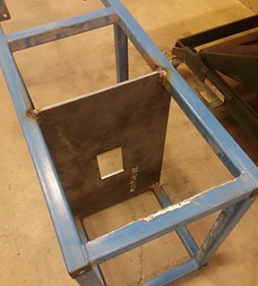
With the kind assistance of my friend, Nelson, who is an experienced welder, the plate was MIG welded at a convenient height. After welding, I abraded and cleaned up some of the welds. I also removed one of the lower frame members to allow for ease of access during milling. In my design planning at this point, I hadn’t accounted for wheel height. I’d planned the plate at a height above my mash tun, so I could place it underneath and mill directly into my mash tun. At the time, I was planning to spray in hot water from my hot liquor tank in a fan shape across the top of the tun. Once wheels were added, they increased the height and dashed my plans. I’ve since upgraded to a 21-gallon (80-L) stainless mash tun from Ss Brewtech and would not be keen on lifting that tun when full. I recommend a close or tight seal between the base of your mill and whatever you’re milling into. It kicks out a lot of statically charged grain dust and debris.

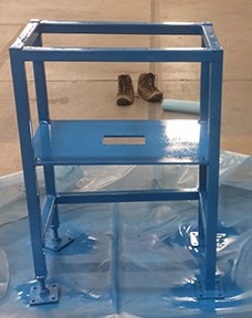
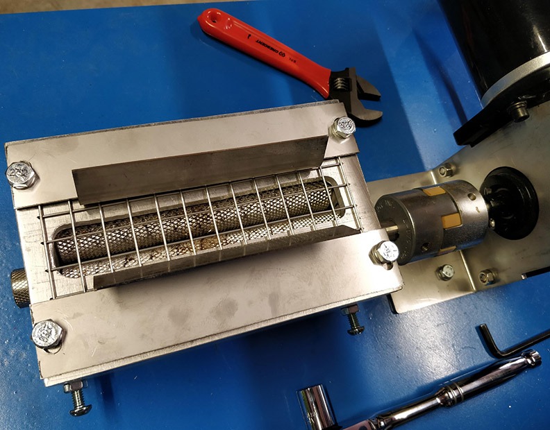
After a few coats of spray paint, I started to install the Monster Mill. I cut, drilled, and tapped holes on some 3.5-inch (88.9-mm) aluminum stock to make the sides of the Monster Mill. I used stainless steel hex fasteners bolted under the mill (in hindsight, I should have countersunk some flat head fasteners for a flush surface).
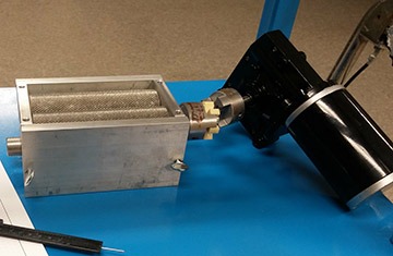
Once the mill was installed, I measured the height to the plate from the mill shaft and estimated the location of the motor. I designed two stainless brackets that bolt directly to the recently installed plate on either side of the motor face. Note that when tapping into any metal you should go slowly, back out one turn every few turns, and use a lubricating cutting fluid. To join the two different shaft sizes (12 mm, 12.7 mm), I used a spider coupler. This three-part device fastens to each shaft and transfers power from motor to mill and allows for a small amount of misalignment, among other benefits.
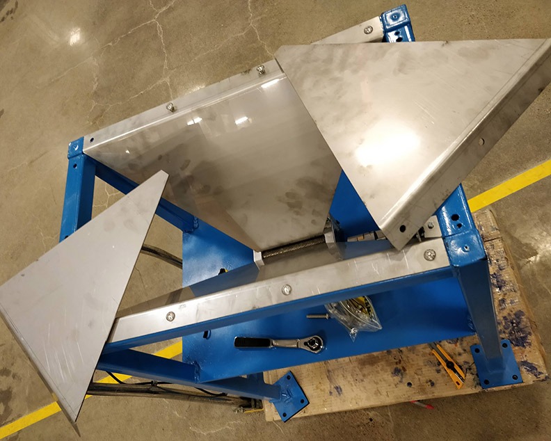
I designed a 4-sided hopper, edge brackets, and a top-mounted guide to try to mitigate any grain dust dropping through gaps in the sides and bottom. This was a challenge in a CAD environment, as the angles compounded and my frame wasn’t symmetrical, nor was the mill placement on the plate (by design to allow for the motor). Part and assembly drawings can be found in a link at the end of the article. After a few design iterations I ordered the stainless from another sheet metal shop to be laser cut and bent. For the top plate of the mill, I jigged a piece of ¼-inch (6.35-mm) aluminum with a routered slot to match the hopper opening. I added some 3/8-inch (10-mm) opening stainless mesh to make sure I don’t get any fingers milled. In practice, this can bridge with malt and stop the hopper from feeding the mill. With the mesh in place, I have to keep the grain moving. I may end up removing it. A steeper hopper may help alleviate this issue.
With my stainless hopper sheets in hand, I bolted the long edges to the frame first using M8 x 50-mm stainless button head cap screws, washers, and locknuts. Other than a few holes being slightly misaligned it went together pretty well. The smaller sides went in next, then I drilled holes to attach the hopper edge brackets with M4 x 10-mm button head cap screws and locknuts. The complexity of designing the asymmetrical components and fit up of the edge brackets had me leave the bolt holes to drill myself. I wasn’t confident I could correctly align the holes when assembled. Once in place I slid the top-of-mill-mounted hopper guides in and bolted them down tight using their oval holes.
My next milestone to get to a test run was to build the electrical enclosure. I selected a plastic enclosure from Polycase that would fit nestled in under the hopper, opposite the motor. I also laid out the components in CAD to ensure my 500W power supply would fit.
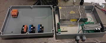
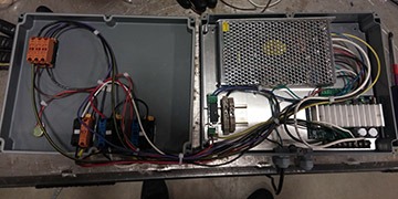
Note that if you wire the negative (red, source) wire to the wrong motor pole, the motor will run in reverse. I learned that you need to wire lights in parallel so they all get full voltage. I also didn’t wire the holding relay correctly. When a momentary pushbutton applies voltage to the relay, it latches in place and holds the circuit on. The “full stop” button, or the E-Stop aka “red alert” cuts power to the holding circuit. This is a smart solution in case of power loss, as the motor won’t energize automatically when power is reapplied. If you review the wiring diagram linked at the end of the article, you’ll see that the red alert button kills power to several locations ensuring the motor stops. Only opening the circuit to the power supply (for example) would still take a few seconds to de-energize when pressed. I was really happy with how the finished control panel turned out.
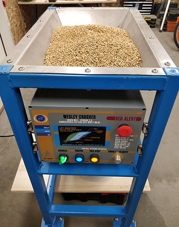
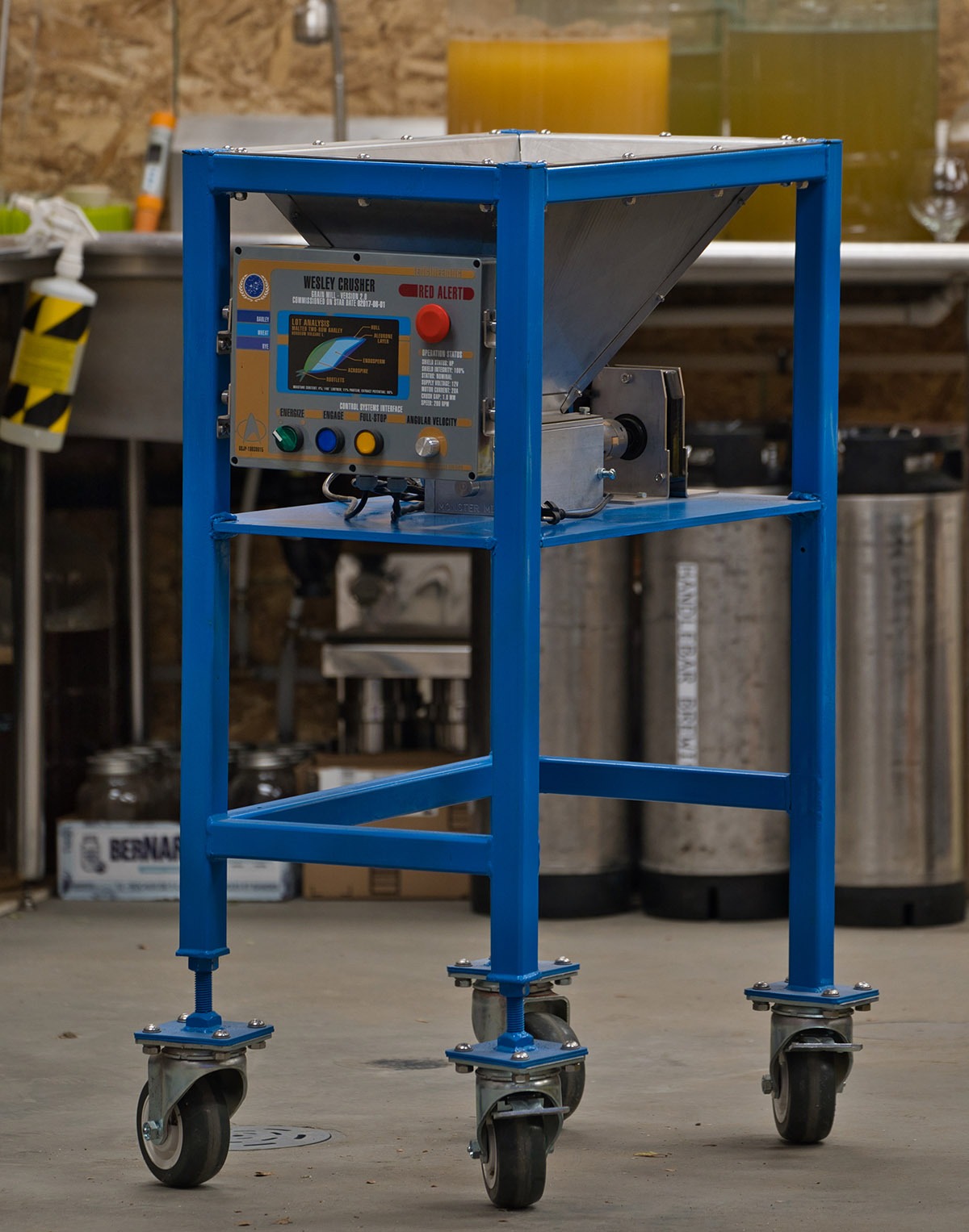
In my early design sketches I chose to design a Star Trek: The Next Generation LCARS-style interface with physical light-up pushbuttons. This fit the theme nicely, as even my early malt mill builds were named Wesley Crusher. I used a transparent adhesive printed label from a local print shop to apply it to my enclosure. Digital artwork is linked at the end of the article.
The last thing to do was to mount the control panel in place. I elected to use some shoulder bolts (think Frankenstein’s monster’s neck) into the sides of my control panel. I designed some forked heavy gauge stainless brackets that would allow the enclosure to be removed easily if needed. It also allowed for some play in the odd shapes in the design, and misalignment. Once installed a light tap had it in place, and this project is a wrap!
This project cost me about $800 (thanks to the free steel plate), although I have been working on it for a few years to get to this point so some of the prices have risen since I bought them. The stainless hopper was the largest expense, with the mill and motor being the two other biggest ticket items.

Links:
• Link to CAD file on GrabCAD: https://bit.ly/BYO22-GM-CAD
• Link to PDF of mechanical/electrical drawings: https://bit.ly/BYO22-GM-PRINTS
• Vector file of enclosure LCARS sticker: https://bit.ly/BYO22-GM-LCARS