Build an Electric Brewing Control Panel
Homebrewing can be as simple or as complicated as you want it to be. Of course, the definition of simple or complicated all depends on the way you look at it. Like most of us, when I started homebrewing, my first batch was brewed all manually with a directly-fired mash tun, keeping an eye on the mash temperature and constantly tweaking the flame intensity for temperature control. Some say this is the simple way but I disagree. It was pretty hard to keep a constant mash temperature. In my case, I find that the use of some basic electrical-electronic tools really does make homebrewing simpler. This article reviews some basic considerations for building an electrical control panel and integration of electrical components.
Safety First
If you plan on simplifying your homebrewing methods using anything electrical, the first thing that should come to mind is your safety. If you are not experienced with electrical wiring, get a professional to help you with this project — do not attempt to do any electrical wiring yourself. Choosing a properly rated electrical enclosure to house/protect your electrical components is also very important — read on.
Choosing an Electrical Enclosure
Naturally, one of the first decisions to be made is choosing the physical size of the electrical enclosure that will contain all the electronics. To determine this, make a headcount of all the electrical components that your system currently uses and leave yourself some room for future expansion. There will always be one more thing to add on. I would suggest that a homebrewing system using a temperature-controlled hot liquor tank (HLT) and mash tun with electrical outlets for pumps fits inside of a 12-inch high x 12-inch wide x 6-inch deep enclosure.
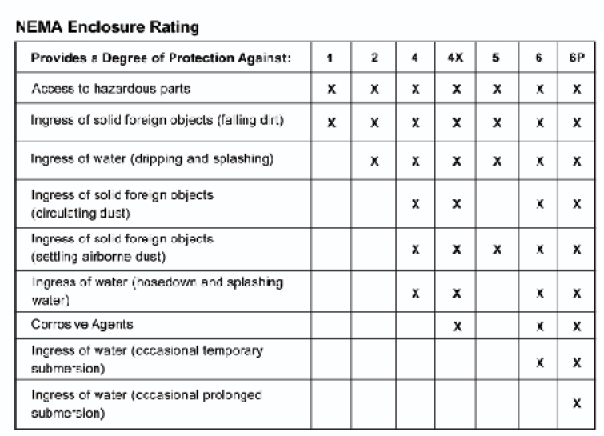
Once you have decided on a physical size, the next consideration will be the type of electrical enclosure. The National Electrical Manufacturers Association (NEMA) provides a rating system for electrical enclosures according to their degree of protection for different environments. Table 1 (below) shows the level of protection of some electrical enclosures. I recommend using a NEMA type 4 enclosure because I don’t find a significant difference in price going from NEMA 1 to NEMA 4, and the fact that this enclosure provides protection against the moisture hazard present in typical homebrewing environments. A NEMA 4-rated enclosure can be used either indoors or outdoors.

Now that you have a physical platform to centralize your system, it is time to decide what kind of electrical components are necessary to control your tools (pumps, heaters, etc.). In the following, the most commonly used electrical devices are discussed as it applies in a homebrewing context.
Electrical Switches
A switch is an electrical device that can break an electrical circuit by interrupting current. In general, switches are classified according to the number and arrangement of their contacts. These contacts are said to be closed when current flows from one side of the switch to the other (electrical device ON), or open when no current can flow through it (electrical device OFF). This is the simplest form of electrical switch, known as a toggle switch used to manually turn on/off electrical devices. There are normally closed and open switches. A switch that is equipped with a double electrical contact is known as a double pole switch. A double pole switch can be used to start two different electrical devices with the push of a single button. By application switches can also be classified by the type of process they help to control (i.e. flow switch, float switch, pressure switch, etc.).
Some of these switches and their possible applications in homebrewing are described in more detail here:
Float Switch: This type of switch closes its contacts when the fluid level reaches a certain level in a tank. These switches are usually electrically wired to a pump for level control, such as overflow protection when filling a tank, or preventing a tank from emptying below a certain level. In a homebrewing application, a float switch can be used to control the sweet wort level of a grant (a small buffer where wort drains by gravity out of the mash lauter tun — this prevents a pump from drawing vacuum by sucking directly from the grain bed).
Flow Switch: This type of switch is normally placed in-line to detect liquid flow. When liquid flow is detected, its contacts close, which can be used for energizing or de-energizing other devices. In homebrewing this type of switch can be used to improve the safety of a recirculated infusion mash system (RIMS). In a RIMS system, a recirculation pump is used to pump hot wort during the length of the mashing process. In the event that this pump overheats and stops pumping wort (or may be clogging with grain husk), and the temperature controller fails to turn off the electric heater, overheating can occur which can burn out the heater and possibly all the wiring back to the main electrical breaker. This would not happen if a flow switch is used to turn on the electric heater. Under this scenario, if the pump overheats and stops pumping, the flow switch opens the circuit which automatically turns off the electric heater. Another safety advantage of a flow switch is that it
will prevent you from dry starting the heater.
Electrical Fuse
Fuses are current limiting devices that are used to open a circuit and stop current flow to a system in the event that the current capacity of a system is exceeded for any reason.
Temperature Controllers
 Due to the precision required in the brewing process (±1 degree Fahrenheit or less), electronic temperature controllers are most suitable. The photo here is a proportional integral derivative (PID) controller. When choosing a temperature controller of this type, the following things need to be considered:
A. Power Supply: Normally these units will operate with anywhere from 120–240 VAC.
B. Input Type: This is the temperature sensor that will be feeding a signal to the temperature controller. The typical options are thermocouples and resistant temperature detectors (RTD) sensors.
The thermocouple sensor consists of two dissimilar metal wires joined at one end. When the junction of the two metals is heated or cooled a voltage is produced that can be correlated back to the temperature. The RTD sensor consists of a resistor that changes its resistance value as its temperature changes. In comparison, RTD sensors produce much more stable and accurate signals (accurate within 0.3 degree Celsius vs 2.2 Celsius) than thermocouples but they are also more expensive. Still, thermocouple sensors may be used for accurate measurements in brewing because most commonly available electronic temperature controllers have signal conditioning circuitry to improve the stability and accuracy of thermocouple sensor outputs. Essentially this makes thermocouples nearly as accurate as RTD sensors. One example of a temperature controller with very good thermocouple signal conditioning is the Auber model# SYL-3242, which improves the quality of thermocouple signals up to 0.2% accuracy (that is within ±0.25 °C or ±0.5 °F).
C. Control Mode: With these temperature controllers at least three types of control options are available, PID, manual or on/off. P, I and D represents a parameter input into an algorithm that calculates and controls how the system should properly respond to disturbances that affect the variable being controlled. For example, mash temperature cools because of heat loss to the environment and this change results in the controller sending an output to a heater.
The following is an analogy of what the PID parameters would do in practice for controlling mash temperature in a directly fired mash tun:
Pretend you are getting ready to begin mashing in with a directly-fired mash tun. Initially, you use the flame
at full power to heat the strike water. When getting within a few degrees from the desired mash strike tem-
perature, you either turn down the flame or cycle on/off to prevent overshooting this temperature. In PID
control mode, this is known as the proportional band (P). After the controller enters into the proportional band, it will turn the heater on/off for periods of time that proportionally correlate (this is known as time proportioning method) to the amount of error (how far the measured temperature is from desired set point).
For example, when mash temperature is 1 °F below set point, the controller will turn on the heater for 10 seconds; when mash temperature is 2 °F below set point the controller will turn on the heater for 20 seconds and so on. Another form of proportional control (P) is the analog 4–20 mA method. Using this type of proportional control, the degree of opening/closing of an electromechanical valve may be controlled in proportion to the amount of error. This would be used to modulate the intensity of a heating flame. However, because the proportional (P) control parameter relies on the amount of error to produce an output, it will never really reach the desired temperature, and that is when the integral (I) parameter kicks in. The integral (I) parameter summarizes the error, which is then subtracted in the algorithm. This brings the measured mash temperature much more closely to the desired set point. At this point, the amount of error (desired temperature vs measured temperature) is greatly reduced but there may be still some temperature overshoot.
To prevent overshoot, the derivative (D) parameter keeps track of the rate of change in mash temperature and
plugs this information into the algorithm. By knowing how fast the mash is heating up, the controller can then predict how far in advance to turn off the heater (or valve throttling when using analog 4–20 mA outputs) to prevent temperature overshoot. All these parameters are automatically calculated and adjusted (tuned) to fit your process. This works best in most circumstances but in certain cases, making adjustments to these parameters (P,I,D) to achieve the best control without overshoot, the controlled system may take too long to reach the desired set point.
If the heating times are not satisfactory to your mash process, you could then run the temperature controller in manual mode. This would allow you to manually modify (tune) the PID parameters as you see fit but this is no easy task. If you feel like going this route, it would then be a good idea to study the topic of PID tuning in depth and practice with online PID simulators before attempting anything.
The last and simpler alternative is to run the controller in on/off mode. If your heater is sized correctly (it heats up the mash at a rate no higher than 2 °F per minute), this is the way to go. Under this scenario, even if the controller turns off the heater 15 seconds after the mash temperature reached the set point, this would only overshoot by 0.5 °F degrees, which is more than acceptable. Sometimes, simple is better.
D. Output Mode: This refers to the type of electrical output used by the controller to manipulate the controlled variable (temperature). The options are SSR (solid state relay), electromagnetic relay and analog signal 4-20 mA (other forms of outputs are available such as DC pulse and 0-10V are available but they will not be discussed here.) When going with SSR output, the controller will not have any power to directly turn on/off any sizeable electrical devices. In this case, the controller only outputs an electrical signal to the SSR relay, which then turns on/off the electrical device. The SSR output mode option is used for high speed switching of loads, where a very high degree of accuracy is required. For example, when controlling an electrical heater, using a SSR relay the controller can order the on/off state of the heater up to hundreds of times per minute to prevent the smallest degree overshoot (this extreme case is really not necessary for beer brewing). The electromagnetic output mode option is used to control slower acting outputs. In some cases, the controller itself is able to run small electrical devices (typically less than 10 amps at 120 VAC) using an internal electromechanical relay. When electrical loads are bigger, this internal relay needs to be wired to an external electromechanical relay. One example of this is the same scenario of using the electric heater to control the temperature in a mash tun. As mentioned earlier, if the heater is adequately sized and its maximum potential to heat up the mash is 2 °F per minute, then the ‘slow’ acting electromechanical relay is appropriate for working with on/off control. The analog control output 4–20 mA signal is used in applications where proportional valves are being controlled to modulate the flow rate of fluids. For example, this could be used to regulate the flame intensity in a directly fired mash in response to measured temperature. Under this scenario 4 mA results in a closed valve and 20 mA results in a fully open valve. Anything in between results in a proportional degree of valve opening.
Relays
 A relay is a load switching device used when the electrical load of a device being controlled exceeds the power rating of a controller. Relays can be very broadly classified as SSR or electromechanical relay. For illustration purposes, this photo shows a SSR vs electromechanical relay. The difference in operation was described earlier. The differences in installation will be described here. SSR relays produce a large amount of heat and this heat needs to be dissipated for its proper operation and lifetime. Every SSR relay should be mounted with a heat sink directly to the back side of it. The heat sink should also be properly sized and will usually be sold as a combo (SSR + heat sink).
 Electrically both types of relays are wired very similarly. The illstration here shows the electrical diagram of an electromechanical relay. When coupled to a temperature controller, terminals #1 and #2 of the relay are connected to the output of the temperature controller. The electrical controller outputs an AC (alternating current) or DC (direct current) signal that energizes this coil. In turn, this energized coil creates a magnetic field which causes terminals #3 and #4 of the relay to switch from open to closed position and turns ON an electrical device. When the electrical coil is de-energized, contacts #3 and #4 open and the electrical device turns OFF. SSR relays do not have an electrical coil (but a photo diode) but the wiring is still done basically in the same way.
Electrical Safety and Grounding
Electrical grounding is of extreme importance, not only for personal safety, but for proper functioning and protection of electrical and electronic systems. Effective grounding creates an electrical environment containing low levels of electrical noise and enhances the safety and performance of electrical and electronic equipment. The ground is the common potential point for all data and process control systems. It prevents interconnected systems from operating at different reference voltages.
The following are three basic aspects of electrical safety:
1. Personal Safety
Extreme caution should be exercised when assembling and testing electrical and electronic systems because of the hazards of electrical shock. Major concerns are overloading and/or over-fusing of electrical circuits, and not having adequate circuit breaking systems in place while doing installations, repairs and testing. When dealing with moderate to high voltages and currents, it is highly recommended that gloves and other insulating gear be employed. It is improper to assemble, install and operate electrical and electronic systems in a wet environment since water can be a good conductor of electricity.
2. Grounding
 Electrical and electronic systems grounding provides for proper protection and operation of all electrical and electronic systems. Electrical and electronic systems are generally divided into three major component systems: power, control and load. Each of these components must be grounded. This illustration shows the electrical symbol for ground.
Grounded systems are usually divided into two major types: electrical and electronic. Electrical grounding is a connection to a neutral point, generally the earth. The major purpose of such grounding is to provide a safe path for fault currents, static discharges and interference signals. A good ground is of extremely low resistance, that is, it is highly conductive. In the event that a high voltage wire came into contact with the metal housing of your electrical enclosure, the fault current would return to the ground via grounding wire of your electrical enclosure (instead of going back to the earth through you!). Because there is very little resistance for this current to flow back to the source, a very high amount of current begins to flow back to the source through this circuit, which quickly triggers the circuit breaker off. Electronic ground is to ensure that the circuits and systems within an enclosure are protected and operating properly, especially for signals and controls.
What makes electronic control systems different is their sensitivity to small transient voltages and currents and also static electricity. There are two types of grounding with these types of systems: a) safety grounding for fire and transient discharges b) performance grounding for protection of circuits and signals. These types of grounding do not have to involve an earth ground or grounding for the power system. Performance grounding usually employs an isolation transformer and proper shielding to achieve the needed protection.
3. Ground Fault Circuit Interrupter (GFCI)
This is the second line of defense after grounding. A ground fault occurs when an unintentional path for current travels to ground other than the system ground path. In an ideal world with a perfect ground, this would never happen but the truth is some corrosion may develop in the ground circuit over time. If the ground fails to bring all the current back to the source, there is still some current that may leak out of the circuit. If this happened and you were touching the metal electrical enclosure, some of that current could travel back to ground through you (shocking you). What the GFCI does is to measure how much current is flowing through the hot line (L) and compares that to the neutral line (N). If these are not the same, it interprets that some of that current is available to electrocute someone, therefore, it shuts off the circuit instead. This is why GFCI’s are an important safety line.
Basic Electrical Control Panel and Wiring
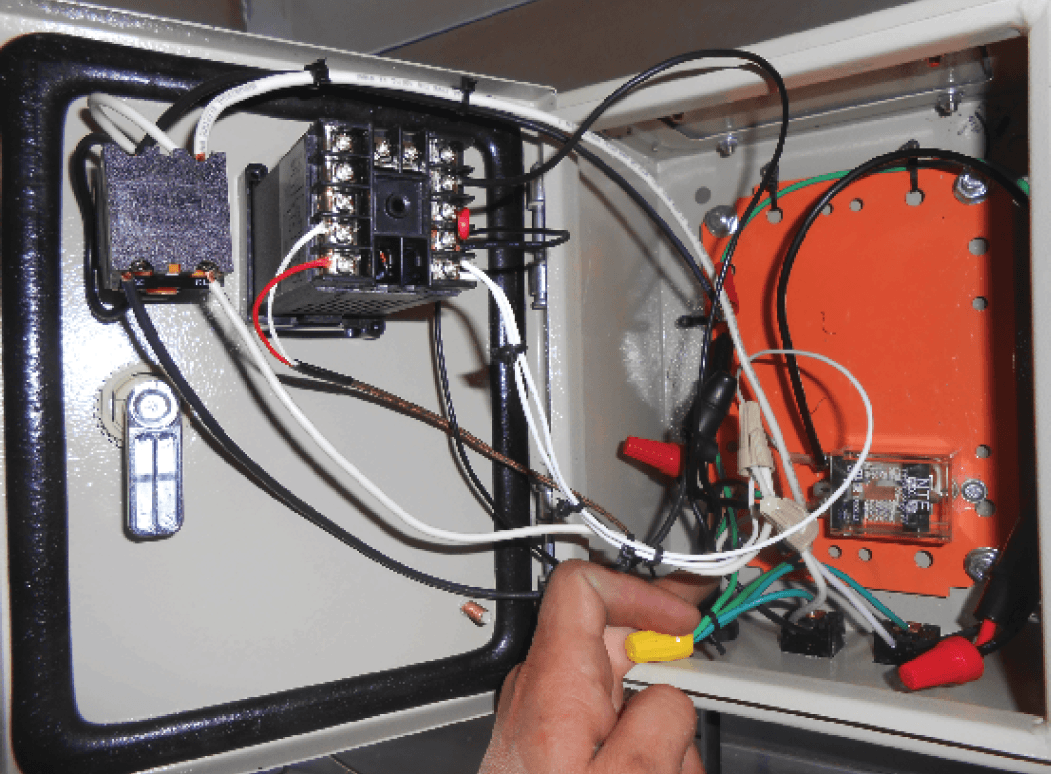
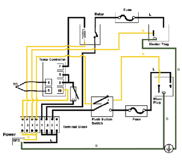 Here is the electrical diagram of a simple electrical control panel is shown. Only two electrical circuits are integrated: a fused turn on/off switch for a mash mixer drive and an automatic mash temperature controlling circuit. The photo below shows the same electrical panel as seen from the outside. The brewing system controlled by this panel consists of a stainless steel mash tun wrapped by an electrically heated jacket. The mash is continually agitated by a top entry mash mixer to maintain a stable temperature. This would be the same circuitry necessary to run a RIMS system, where the temperature controller controls an in-line electric heater. Instead of the mash mixer, there would be a wort recirculation pump. A temperature controller with a type J thermocouple input is used to monitor the mash temperature and heat is added to the mash as needed to keep a set point temperature within a 0.5 °F margin.

The electrical wiring diagram and mash temperature control logic is as follows:
1. Mash Mixer Circuit. The mash mixer is turned ON by pushing the Mixer Start button. This is a double pole switch. Both the neutral and hot wires run through it (the reason for using a double pole switch here is to operate a light indicator internally wired in this particular switch, which illuminates when the device in ON.) Pushing the start button closes the contact to the hot line (L) to the mash mixer circuit.This passes current through the inline fuse to the mixer. Once the current gets to the electrical motor in the mixer, it flows back to the power terminal block through N-line. This current flow is what causes the mixer to turn ON. The green wire (ground) from the mixer is connected to the electrical enclosure frame.
2. Temperature Control Circuit. By pushing the controller start button (single pole switch — black button to the left of controller), the temperature controller is powered ON. Again this closes the contact in the hot line (L) to the electronic temperature controller, allowing current to the controller, which then returns to the power electrical terminal through N-line. This current flow is what causes the controller to turn ON.
The temperature controller was turned ON so it can now read the thermocouple signal and compare to desired set point. If set point is lower than measured temperature it will output a signal on terminals #7 and #8 to turn ON the heater. The controller does this by closing internal contacts between terminals #7 and #8. This allows current from L-line to bypass from terminal #8 to #7 and then flow to the internal coil in the relay. This current then returns to the power terminal block by neutral (N) line. When current flows through this coil, it
magnetically closes the internal contacts in the relay which bridge the hot line (L) power to the electrical heater (passing through electrical inline fuse first).This allows current flow to the heater, which returns to the power terminal block through the neutral line (N). When mash temperature is equal to set point, the contact in the terminals #7 and #8 inside the relay opens up, which stops current to the coil. This opens the hot line (L) to the heater and shuts it off. The green wire (ground) from the electric heater is connected to the electrical
enclosure frame.
