Building a Cold Room

Early in 2020 my keezer was at the end of its life and struggled to keep my kegs cold. The timing was apt, as I was planning to move to a new home and build a brewery-oriented garage. I considered three options: Replacement, upgrading to a 3-door fridge, or upgrading to a full cold room. The cold room had the clear advantage for space, access to taps, heat and noise generation, and planned layout, and was the direction I ended up going. Now complete, I thought it may be helpful to run through the design choices and features for others who may be considering their own cold room upgrade.

Above is my concept model from early in the design phase, showing the brewery side of the garage. Left to right, you’ll see the cold room concept with six taps, storage racking, fermenting fridge (BrewPi-driven, arduino-controlled), 3-vessel electric system, my second-hand L-shaped sink, and my malt mill. The cold room would have an internal footprint of 6.5 x 3.3 feet (2 x 1 m), with 43 square feet (4 m2) in volume. This is compact enough for my needs, and much smaller than any commercially available cold room like those from CoolBot. I planned in space for six kegs on tap, six on reserve, a rack for my bottle cellar, and a cold water reservoir for chilling needs in the future.

The garage has a glycol-heated concrete pad, so when laying that plumbing the area around the cold room was avoided. The only other consideration in the garage-build phase was to include a small window opening for the through-wall air conditioning unit. The cold room frame was built after the outer shell of the garage was up, with the door opening sized for a commercial door in case I was able to find a used one.
The garage construction has 2×6 wood studs, so I kept to that for the cold room. Since an R-value of at least 25 is recommended by the CoolBot manufacturers, I also included an internal 1-inch (25.4-mm) rigid foam layer. Remember to always put your vapor barrier on the warm side of your construction — for the cold Canadian winters where I live in Saskatoon, Saskatchewan that meant only inside of the outdoor-facing walls got barriers. The walls and roof of the cold room that face the inside of the garage also got an outer vapor barrier layer. Inside and outside were shelled with a 7⁄16-inch (11.1-mm) oriented strand board, OSB. Then a fiberglass reinforced plastic (FRP) called Exceliner FRP went up, which lends a clean, professional, finished look, as well as a beer-proof shell.

SAFETY ADVISORY: Wear breathing protection when cutting fiberglass, use function-specific circular saw blades (or an oscillating tool for detail cuts), and make sure all your dust and waste gets bagged and goes into the trash — not outside into the environment. Be sure to wear gloves at all times, as exposed edges are quite sharp.
As cut sheets, the FRP was good to work with. It is light, flexible, strong, and resilient. Panels are adhered to the OSB substrate with a water-based adhesive. Only the vertical surfaces needed to be supported during cure, the rest stayed adhered after applying pressure with a dry paint roller.
Having selected some components and layout early, I’d included a few handy features. I wanted to have distributed plumbing throughout my garage (air, water, sewer, compressed air, ethernet, CO2), so I knew my CO2 tank would need plumbing from the attic. I added two bulkhead fittings to plumb CO2 though the cold room walls. The entire room runs on one GFCI 120V circuit, and the air conditioner has a dedicated 240V circuit sized for my A/C unit. I included a ceiling-mounted outlet for plugging in the CoolBot, and a RJ12 junction box leading above the cold room for the CoolBot Pro Wi-Fi module. I also included an outlet on the large wall where I planned to have a cold water reservoir and pump for a fermenter and brew day cooling loop. Note there are grommets on the outer wall for two PEX tubes for that expansion, which will be a project for another year. I also included an ethernet jack and AC outlet to the front wall to eventually build a Raspberry Pi-based tap list.

A cross-section view of the taps shows that I made a cutaway for the shanks. In hindsight I should have just bought longer shanks and used a full-thickness wall. It was a challenge to finish with the FRP, reduces my insulation, and as designed, relies on the compression resistance of the rigid foam. It has been a challenge to keep my shanks tight as the foam compresses. Longer shanks are chrome-plated steel instead of stainless — but I’d rather replace them periodically in the long run if I had it to do over.
By the time the main construction was complete, I hadn’t had any luck finding a used commercial door. I quoted new ones at around $2,500, which was more than I was willing to pay. Plan B was to design my own triple-sealed door.
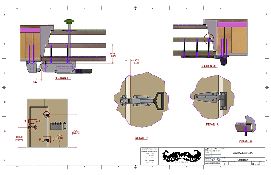
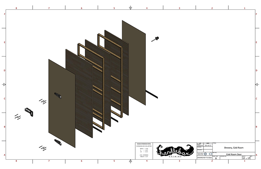
Turning back to my 3D model I started to design the thicknesses, angles, heights, and widths of construction to allow the door to swing open without interference. I’d selected my door hardware and modeled it in 3D as well to aid in the design and ensure mounting would line up. The door is built from premium thin-layer ¾-inch (18-mm) maple plywood and the same rigid foam from earlier in the build (double layers between plywood). I copied the step design for the top of the door as well for simplicity. The bottom of the door has three weather strip floor seals. Cutaway drawings to the left show the door open action, and the need for the angled steps. The door jam also needed to be custom from treated lumber. I used 2×6 and 2×8 lumber that was planed, cut to shape, glued together, sanded, and painted.
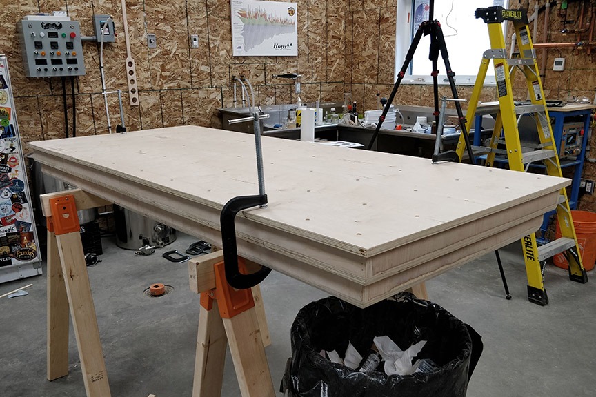


The rest of the door is two torsion boxes assembled with a pneumatic pinner, adhesive, and some heavy duty long wood screws all anchored to the middle layer of plywood. I used some long stainless steel oval-head screws for mounting the main hardware. The door was assembled from the inner layer outward, shimming the bottom and sanding the edges to fit evenly in my door jam. Links to more photos of the construction process and a short time-lapse video illustrating the stages the door was constructed in are included at the end of the article.
With the door and weather stripping installed, the next step was to start up the air conditioning and test out the CoolBot.
I’d intentionally oversized my air conditioner out of due caution, but that seems to have driven my air temperature to drop below freezing briefly during cooling cycles. I haven’t seen any ill effects from this as the freezing temperature doesn’t last long. Even on hot summer days, the system only turns on about once per hour.

Inside the cold room isn’t large but it feels great and looks amazing. It will eventually get epoxy floors along with the rest of the garage.
To get this cold room build operational, I estimate it cost me $4,500 CAD ($3,600 USD). I already had the WilliamsWarn counter-pressure bottle filler and a dozen kegs. The LED light is a 6,000 lumen 50W fixture, and is excellently bright. A link to a full bill of materials (in Canadian dollars) is at the end of the article, but here’s a quick summary:
Exceliner FRP, trim, and adhesive ($900)
Kason door hardware ($900)
Insulation ($225)
2×6 framing ($200)
Air conditioner ($800)
CoolBot Pro ($400)
Perlick taps, shanks ($300)
Drip tray ($540)
CO2 tank, lines, regulators, manifolds, and accessories ($300)
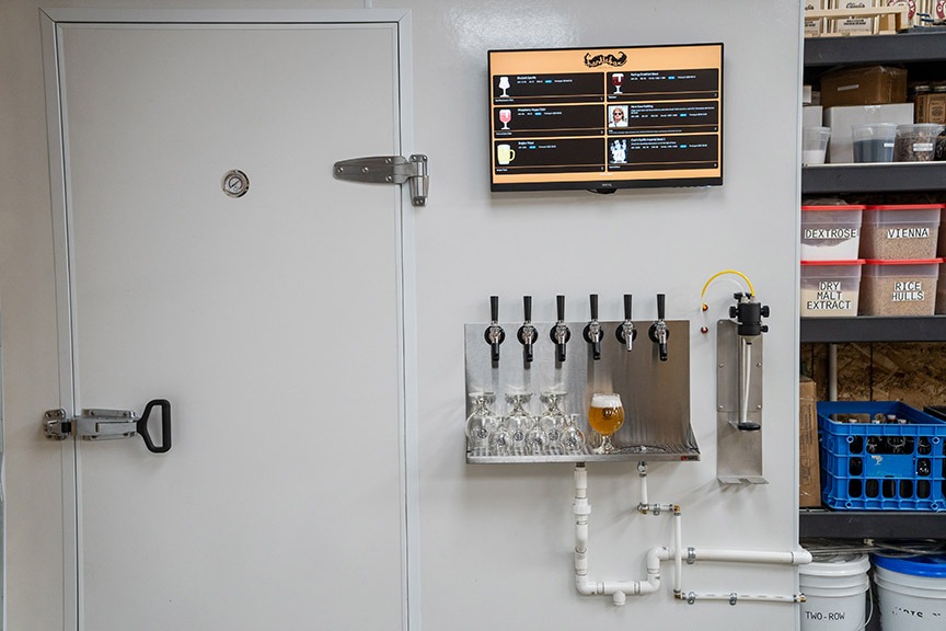
After planning to have a chalkboard tap list, I stumbled upon tapit
good.com, a web-based tap list. Its interface is easy to use and it looks good. You can program in your beers and add or remove them from the list at any time. There are also several integrations with various software — hopefully more to come. I invested in the annual subscription fee of $20 for more than four taps and installed a computer monitor, and Raspberry Pi programmed to boot full screen to my page, which can be seen in the picture at the top right.
Want to see more of this build? Visit these links:
• Cold room and door dimensioned drawings: https://bit.ly/GP-BYO-ColdRoomDrawing
• Bill of materials: https://bit.ly/GP-BYO-ColdRoomBuild
• Build video: https://youtu.be/-n3YAtKM7w8


