Build an Electric Brewing System

When I started thinking about a return to homebrewing, after a nearly-15-year hiatus, I started my research diligently to see what has changed since I got out of the hobby for a variety of reasons. During my first stint, I brewed 10-gallon (38-L), all-grain batches using traditional propane burners with a keggle and a converted Igloo drink cooler for a mash tun. I knew I wanted to make things a bit easier this time around so I wouldn’t spend my day hauling and lifting heavy pots full of nearly boiling water, but I had no idea what was in store for my new setup.
My friends and family will tell you that I am a bit of a research nut, so it was no surprise to them that once I decided to build a new homebrewing system, I spent a significant amount of time on the Internet looking at systems and equipment that other people are currently using. I was expecting to see more of the same as I had been using in the past, with maybe a few new ideas thrown in; what I wasn’t expecting to find was an all-new way of brewing using electrical water heater elements along with varying levels of automation to control the amount of heat being applied. I was instantly impressed and amazed at the brewing systems I saw, and knew almost instantly that electric brewing was the way I wanted to go. Being from Minnesota, electric brewing instantly made sense to me: I could recall many times in the past when my homebrew friends and I spent hours standing on cold cement in a frozen garage with the door halfway up while brewing, wearing winter jackets and hats. The thought that I could brew indoors, in a climate-controlled environment, all while not having to listen to the jet engine sound of a propane burner, finalized my decision and set the wheels of progress in motion. Here is my system from start to finish — hopefully it will inspire you to build your own!
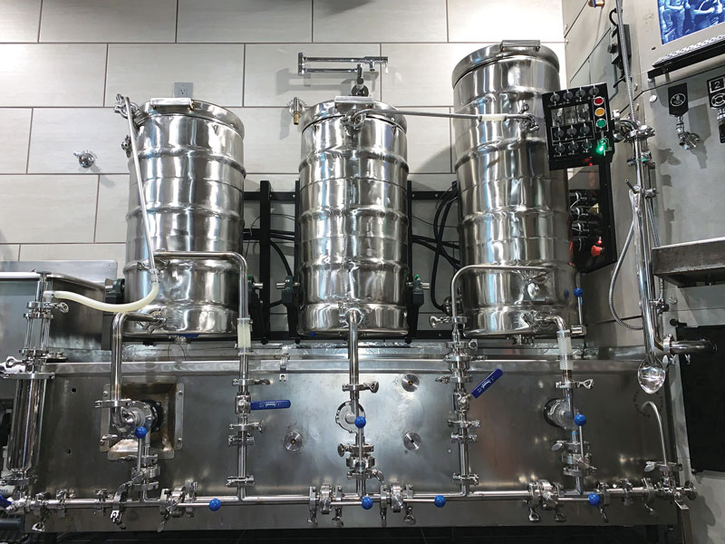
Most of my build is fairly standard, utilizing a pair of Chugger pumps, three stainless steel vessels, and a RIMS (recirculating infusion mash system) tube all on a single-tier stand, much like the common “Brutus” style of builds. But instead of propane burners installed underneath the kettles, both the hot liquor tank (HLT) and the boil kettle have 240v 4500w ULWD (ultra low watt density) water heater elements installed inside of them as the heat source (see photo above).
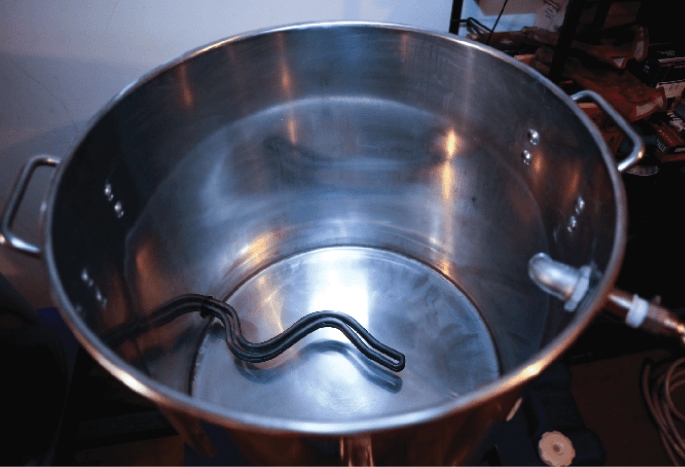
The nice thing about going all electric is that the heating element is in direct contact with your water or wort, so the efficiency of your heating method is much higher than utilizing an external source such as a propane burner (see photo, bottom). This efficiency does have its drawbacks in that you need to be very careful not to scorch your wort due to that direct contact. That is why having a ULWD, or at least a LWD (low watt density), element is so important: These “ripple” style elements have more surface area than a short, straight element, thereby reducing the risk of scorching, but not eliminating it entirely. The third heating element is a 240v 1500w LWD element in a stainless steel RIMS tube that is made specifically for that task by www.brewhardware.com.

I designed the system to utilize triclover fittings for the installation of the heating elements, which was made easy once again with the help of www.brewhardware.com. In addition to their RIMS tube, which has tri-clover ferrules on each end (see photo on the top of the next page), they also carry ferrules for installing in your kettle, as well as enclosures for the actual element itself that make installation simple and the results extremely professional looking. Using this type of system, the electric parts of the element are enclosed for safety, and with proper wiring, it also ensures that your kettle is grounded. An added benefit is that they are sanitary, as they lack any threads where trub and debris can hide, and they are easy to remove for inspection and cleaning purposes.
All of the fittings on the kettles including the triclover ferrules and stainless steel bulkheads were installed professionally in the kettles utilizing tungsten inert gas (TIG) welds. This can be more difficult and expensive to accomplish than using weldless bulkheads and/or soldering, but I had the option available to me so I chose to go with the more permanent solution in hopes that it would reduce leaks and make the system look more professional. Neither way is right or wrong, and many successful systems have been built using all options. In that same vein, I went with fully stainless steel three-piece ball valves, which make them easy to disassemble and clean, ensuring no foreign matter gets into your wort/beer (see bottom photo, right). Another advantage to the three piece valves that people don’t always realize is that when installing a standard one-piece ball valve in a welded fitting, you can sometimes end up with your handle upside down, or on the side when the valve is fully tightened into the fitting. Most times, you can adjust this somewhat, using more force or additional Teflon tape, but if the difference is too great, you simply have to live with a handle out of place. When using a three-piece valve, you can disassemble the valve after tightening it, and rotate the body in 90-degree intervals to get the handle as close to the 12 o’clock position as possible. It may be a minor thing, but the cost wasn’t outrageously more than the alternative, and this added benefit did come in to play on several of my valves when I was assembling the system. To finish out the plumbing, I went with quick disconnect camlock fittings on all kettle, pump, chiller, RIMS tube input and outputs, as well as on all hose ends (see the camlock and fittings photo on page 58). This makes moving hoses around a simple process and always provides a nice liquid tight seal.
As you can see, most of the equipment in my system is fairly standard, and not much different than what you see in a “traditional” gas fired brewing system (see the sidebar for the equipment rundown on page 59). If you ignore the heating elements in the HLT and brew kettle, as well as the shiny stainless steel tube on the lower rail of my stand for a moment, you wouldn’t notice much difference from systems you have probably seen many times on the pages of this magazine, or even brewed on yourself. Both the HLT and mash tun are 15-gallon (57-L) stainless steel pots that are available almost everywhere. The boil kettle is a 20-gallon (76-L) pot of the same make, as I felt the added capacity may be beneficial, now that I was going to brew indoors, in helping prevent any boil overs that would possibly make a large mess on an indoor floor. As you’ll see later, this probably wasn’t necessary as the boil was nicely controlled using my automation system, and I never experienced a rapid out of control boil. But possibly in the future, I may be able to step up to 15-gallon (57-L) batches depending on the grain bill, at which point I would be limited only by the capacity of the mash tun.
For the stand, I built a Brutus-esque rectangular structure to accommodate my three vessels, with a lower rail for mounting the RIMS tube and the pumps. I fabricated it myself out of 2-inch square 16-gauge steel using a MIG welder. You can approach the stand a lot of different ways depending on your system and space. I chose to use a similar design as Lonnie McAllister’s Brutus Ten basic stand (https://byo.com/product/build-brutus-ten-digital-edition): I have four each 66-inch rails, four each 36-inch legs, and eight each 13.5-inch cross beams. If you know how to weld — great! If not, this is a job for the local weld shop. Before you build your stand, make sure that you size everything to accommodate the size of your kettles. This stand shape is not necessary, however, I just like how it looks. Another easier option if you don’t want to build a stand from scratch is to source a stainless steel work table from a restaurant supply store. Look for one with a shelf underneath the tabletop for mounting your RIMS and pumps. Unlike a gas-fired system, your stand doesn’t need space below the vessels for a heat source as the elements are in the vessels themselves. You just need a surface, like stainless steel, that can be exposed to heat from inside the kettle.
Control Box
The biggest difference between a traditional gas-fired brewery and the system you see here really comes down to the “brains” of the system. In my case, this brain consists of a unit called a BCS-460, which was developed and produced by a company called Embedded Control Concepts. When I say this unit is the brains of the system, I am not exaggerating; the built-in logic and control over nearly all steps of the brewing process gives a person complete control, and allows for a repeatable brew process as well. The BCS-460 is accessible through its built-in Web interface and can be controlled via temperature probes in your systems, processes you design and develop, as well as buttons and timers built in to the Web interface. All of these inputs then are able to control both the heating elements as well as the pumps, using relays within the control panel. Pumps are set to an either on or off setting, while the heating elements can be controlled more precisely using PID-like algorithms to reach and hold a specific temperature, as well as a power percentage mode which allows you to maintain a nice easy rolling boil without it getting out of hand, which often leads to a boilover.
Wiring the Box
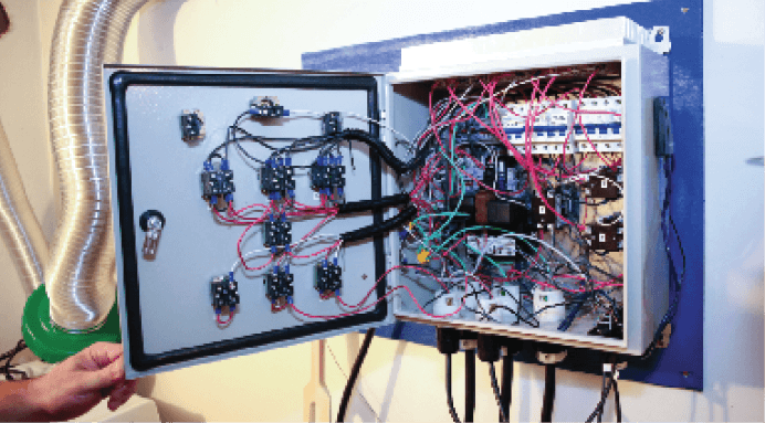
The build of the control panel, which houses the Brewery Control System (BCS) and all of the automation controls, is easily the most complicated part of the build. Fortunately I was not breaking new ground; others had been here before me, and several of them have documented their builds quite nicely. One such person is Kal Wallner, the creator of the website www.theelectricbrewery.com, and while he uses a bit of a different method for automation control, his website and the eBook he has produced are wonderful sources of information and inspiration for anyone who wants to go electric. Another key player in my ability to get things done is Paul Muth, a retired IBM technician/technical manager who goes by the handle of P-J on the homebrew forums found at www.homebrewtalk.com. In my opinion, his wiring diagrams are the benchmark by which all others are judged when it comes to wiring up anything homebrew related. Fortunately for me, he already had a diagram posted that would fit into my plans with minimal modifications (see the wiring diagram below).
In addition to the BCS-460, there are several other key components needed to build an electric brewery panel. The first one is the key to safety when electricity and liquids are used together, and that is Ground Fault Circuit Interrupter (GFCI) protection. For my application, the easiest and best-priced option was to install what is commonly known as a spa panel. These are used primarily for hot tub/pool installations, and are available at most hardware stores, as well as through many online retailers. Most often they are cheaper than installing a GFCI circuit breaker into your power panel, and they can be wired easily into your electric homebrew system. In my case, I was using my existing clothes dryer circuit, so I simply wired the spa panel up to a cord that would plug in to that outlet, and then the panel for the brewery itself was hardwired out the other side of the spa panel. This gave me ground fault protection as well as an easily accessible breaker that could be used to disconnect all power from my control panel if I needed.
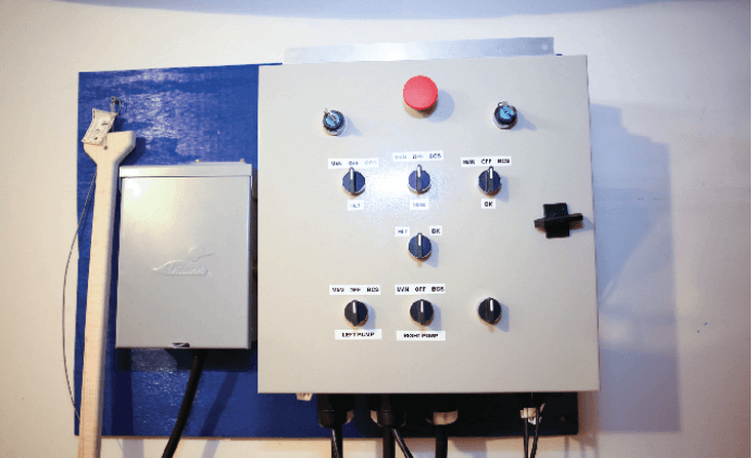
The panel itself started out as steel National Electrical Manufacturing Association (NEMA) enclosure that is approximately 16 inches wide, 16 inches tall and 8 inches deep (40 cm x 40 cm x 20 cm). This will house the BCS-460 as well as all other necessary components. There are many ways you can go with your enclosure, from a simple setup with a few buttons, to those including digital displays for temperatures and timers, all the way to the most elaborate setups that include touchpads on the front of the panel itself. Most of the enclosures will be somewhere in-between, and mine is no exception. I decided to forego any displays on the control panel itself, and instead rely on an external source such as a laptop or tablet. A simple combination of buttons and switches give me all the control I need to augment the BCS Web page control.
At the very top of the panel (see photos below), we start with a large red button, which is an emergency shut off. This button works by diverting a small amount of current to the ground line, which will instantly trip the GFCI breaker and shut off all power to the panel. The button isn’t used for normal on/off operations, but is nice to have in case of an emergency, since it is best practice to keep all doors to both the main and spa panel shut, thereby restricting access to the GFCI breaker. On each side of the emergency shut off are two key switches, which I do not use at this time. The intention of these key switches was two-fold: One was to control power to just the BCS unit, which would allow me to turn it on without risk of firing any elements and/or pumps to facilitate programming the BCS ahead of time for my next brew; the other keyed switch was to be used to power everything else, so in order to brew, both keys would need to be turned on. After installing them I felt at this point they were unnecessary, as I could use the breaker on the spa panel for on/off, and if I needed to use just the BCS, it was only a matter of ensuring a few switches were in the correct orientation prior to energizing the panel.
The next row of switches controls power to the heating elements, with each element having its own switch for control. The bottom rows of switches are the same, but are used for the pumps in the system, and currently only two of these are in use. As you can see, each of these six switches have three positions: Manual, off, and BCS. While in the standard BCS position, all control over the elements and pumps is done through the BCS and the Web interface. This is the standard position for normal operations, but the nice thing is that I can bypass the BCS and turn a switch to the manual position, which will then turn that pump or element on fully. This is handy if I need to fire an element for a short time in order to heat up some water for cleaning, or if I need to run a pump for a short time in order to clean some lines, or simply empty one of my kettles. When I was first building my unit, I didn’t think I would use this manual mode much, but now that I have had it I feel it is an invaluable tool in the cleaning process, and it has some benefits during the brew process as well, including ensuring you get every last drop of valuable wort while reducing the risk of running your pumps dry for extended periods of time.
The final switch on the panel, which is in the center of the panel, is a necessary safety feature if you are using anything less than a 50-amp circuit to run your brewery. This switch ensures that there is no way that both of the larger, 4500w in my case, heating elements can be fired at the same time. Since each element has the capability of pulling close to 20 amps, if I had processes set up within BCS that would fire both elements at the same time, I would easily blow the circuit breaker in my main power panel, which has a max of 30a. So in order for one of the main heating elements to fire, not only does the switch for that element need to be either set on manual or BCS, but the middle switch must also be set to that particular element. Power itself is controlled through a series of normally open switches, solid state relays and heavy duty contactors, as seen in the wiring diagram (featured below). Note: If considering a project like this, please seek the assistance of a professional; you are dealing with large current draws that have the ability to cause serious harm and even death. Each of the heating elements has a dedicated contactor, which ensures absolutely no current leaks through the circuit when it is supposed to be off. A solid state relay (SSR) is used over a standard coil relay due to the speed at which they can operate, but they can leak small amounts of current, which is why a licensed contactor is necessary. The BCS, as well as a Proportional Integral Derivative (PID), can cycle quite quickly in order to keep the temperature at your set point; the SSR is built to better handle these quick switching operations. The tradeoff for this is the amount of heat the SSR will produce, so you need to be able to deal with it properly. For my build I decided to go with a large heatsink mounted to the top of my enclosure, which is 6 inches wide and 14 inches long (15 cm x 45 cm) to help dissipate all that extra heat. This heatsink was tapped, and all six SSRs were mounted directly to it, with a thin layer of thermal paste applied to assist in heat transfer.
Finally each circuit is protected by its own internal DIN mounted circuit breaker, appropriately sized for the element used, while ensuring the wire used is adequate for the circuit and expected draw.
Web Interface
The BCS Web interface (see photo below) gives you a good amount of information at a glance, where you can quickly view your current temperatures, as well as what process or processes are currently running. The interface also displays timers that you can configure, as well as buttons to stop all the processes completely, or simply step to the next process you had previously designed. The BCS-460 has four temperature inputs, four discreet inputs, and six discreet outputs used for controlling your pumps, heating elements, your fermentation chamber, or even your keezer, if you desire. They also have a BCS-462 that increases both the number of inputs and outputs available for even more automation if you want it.
The Process
For my system, I have a temperature probe setup in the output of the HLT, (see photo page 64) which is used to control the HLT heater element while heating up both my strike and sparge water. I can supplement this heater by running the water through my RIMS tube, and firing the heater in the tube, as well giving me 6000w of heating to reduce the amount of time it takes to get up to temperature. Once the water is up to strike temperature, I pause the system using the BCS web interface, and pump the water into the mash tun. The grain is then added and stirred until everything is mixed thoroughly. At this point, the necessary sparge water is then added to the HLT, run through one of the pumps, and heated to sparge temperature using the HLT heating element (see below for the process).
Meanwhile, the mash can proceed utilizing the second pump, with flow going thru the RIMS tube for temperature stability, and back into the mash tun through the Blichmann AutoSparge (see photo at bottom left). Temperature is monitored by temperature probe in the output of the mash tun, and increased as needed by the heating element in the RIMS tube. A standard false bottom in the mash tun prevents grain from escaping, while the constant circulation using the pump sets the grain bed nicely, and allows for a nice clear recirculation. With the temperature control of the BCS, it allows me to precisely hit my mash temperatures, and hold them throughout the entire mash. I can increase the temperatures as needed for any steps or for a mash out if so desired.
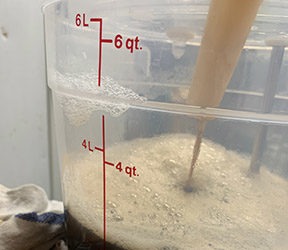
The next step in my process is the sparge, where almost every piece of the brewery is in use at once. Water is moved from the HLT to the mash tun using the first pump, while wort needs to be extracted from the mash tun and pumped into the brew kettle using the second pump. Flow is controlled using ball valves on the output side of each pump, and the Blichmann AutoSparge helps ensure that the mash tun
doesn’t overflow, and will restrict flow into the mash tun if the level gets too high. I can sparge as fast as the grain bed will allow, or I can throttle it back and take longer if I want, to try and extract as many of those valuable sugars as possible.
Once I have sparged enough wort to ensure that the heating element in the boil kettle is fully submerged, I can then start the process of heating the wort up to a boil. This is another advantage I find with the BCS controlled electrical way of brewing: I don’t need to wait until the sparge is complete; I can start heating the wort early in the process, and by the time I am done with the sparge, the entire contents of the brew kettle are nearly at boiling temperatures. When the boil does start, this is another point that the control offered by the BCS really shines. As a brewer who has previously used a gas-fired brewery, even if it was a long time ago, I still vividly remember the smell and the mess caused by the inevitable boilover. The fact that the BCS controlled the boil so well was an unintended but welcomed bonus (see photo above).
Electric Brewing Beats Gas
Overall, the brewing process on my electric system isn’t that much different than what you would normally expect from a gas-fired setup. One big difference, however, is convenience. It has been a long time since I brewed on my old propane-based brewery, but I distinctly remember being completely exhausted at the end of the day. The process of lugging gallons of water around, the loud droning noise of the propane burners, as well as the constant heat they put out normally led to me being hot, wet, and exhausted at the end of the day, and inevitably, many times, I skipped cleaning things up until the next day.
My new system is easier, quicker and overall a lot less mess to clean up. Not all of that can be attributed to the electric setup; simply adding a pump or two to a gas-fired system can make your brew day much easier, but I really feel for my situation — this truly is the best in class for me. I know the next time I have a brew day scheduled, and Mother Nature decides to rain (or snow) on me, I will be thankful for my indoor electric brewery. I’m looking forward to how wonderful brewing year round in the comfort of my temperature controlled basement will be.
Inspiration and Thanks
For this project and story, I’d like to thank Kal Wallner at www.theelectricbrewery.com; Bobby at www.brewhardware.com for sharing his knowledge and numerous products used in this build, including TC and Camlock fittings, tubing, temperature probe adapters and many other unique products; and the incredible people and the wealth of knowledge at the www.homebrewtalk.com forums.
I also want to give a special thanks to Homebrewtalk.com user Paul Muth (aka P-J) for creating excellent wiring diagrams and the incredible wealth of information he provides. He has posted numerous wiring diagrams that have helped so many people while expecting nothing in return but respect.

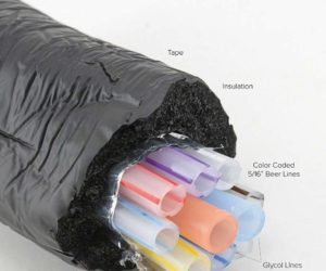
The heat used for boiling water and wort in Trent’s all-electric system comes from inside the hot liquor tank (HLT, above) and the boil kettle in the form of two ultra low watt density (ULWD) water heater elements. The devices are installed using tri-clover fittings.By installing and wiring the heating elements this way, the electric parts of the element are enclosed for safety and the kettle is grounded. This design also ensures that your vessels are sanitary as no trub or debris can gather, and the parts can be removed for cleaning.
Tip: When choosing heating elements to use for your own electric system build, know that “ripple” style elements have more surface area than straight elements, thereby reducing (but not eliminating) the risk of scorching.

In addition to the two hot water heater elements, this system utilizes a stainless steel RIMS (recirculating infusion mash system) tube. The RIMS element has a tri-clover ferrule on each end for easy installation as well as disassembly for cleaning and sanitizing.
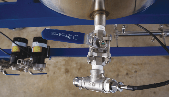
Trent chose to utilize stainless steel three-piece ball valves for his setup, which are easy to disassemble and clean. The advantage to choosing three-piece ball valves over one-piece ball valves is that you run less of a risk of installing the handles out of place.


To finish out the plumbing on the system, Trent installed quick disconnect camlock fittings on all of the kettle, pump, chlller, RIMS tube input and outputs as well as on all hose ends.The quick disconnects give Trent the ability to quickly and securely attach the tubes between his brewing vessels, as well as detach them for easy cleaning and sanitizing.
The camlock fittings and quick disconnects provide a nice tight seal between vessels, and make the process of moving liquid and hoses around Trent’s homebrewery simple.
Electric Homebrewery Components
Hot Liquor Tank: 15-gallon (57-L) stainless steel pot with 240v 4500w ULWD (Ultra Low Watt Density) water heater element
Mash/Lauter Tun: 15-gallon (57-L) stainless steel pot with false bottom and Blichmann AutoSparge
Brew Kettle: 20-gallon (76-L) stainless steel pot with 240v 4500w ULWD (Ultra Low Watt Density) water heater element and a hop spider by www.arborfab.com
All thermocouples (TC) and bulkheads are custom TIG welded into the kettles
RIMS Tube: Brewhardware.com 12-inch kit with 1500w element (http://www.brewhardware.com)
All heating elements are 240v style. The element enclosures utilize 1.5-inch tri-clover fittings, made by brewhardware.com
Pumps: 2 Chugger stainless steel inline pumps
Chiller: CFC chiller by JaDeD brewing (http://jadedbrewing.com/products/the-jaded-cfc)
Brew Stand: DIY MIG welded stand made from 2”x2” 16-gauge steel
Custom DIY stainless steel exhaust hood
Fermenter: Stout 14.5-gallon (55-L) stainless steel
Control Panel: DIY project
Main Control: BCS460 Brewery Control System (BCS) (http://www.embeddedcontrolconcepts.com)
BCS, SSRs, contactors, switches, buttons, relays, temperature probes and enclosure sourced from http://www.ebrewsupply.com/

Panel wired to allow for both BCS and manual control of all pumps and heating elements. It is fully customizable allowing for pumps and heating elements to be controlled via Web interface.
Power input from the main breaker panel is from a 50-amp GFCI breaker via a 4 conductor cable to a 50-amp receptacle. The brewery control panel incorporates circuit breakers as illustrated for circuit protection. The breakers must reside inside the control panel. It is suggested that you install DIN rails in your enclosure and use DIN mount circuit breakers for this installation. DIN rail circuit breakers are illustrated in this plan.

6V DC power cord wire to replace the BCS-450’s 5V DC power if the BCS-460 is not available and you need to run in manual mode.
The “brains” of the electric homebrewery come from a unit called a BCS-460, which is produced by a company called Embedded Control Concepts. The unit is controlled via a multitude of processes, switches, relays, and temperature probes incorporated in the system.

Trent’s control panel is a steel NEMA enclosure that is approximately 16 inches wide, 16 inches tall and 8 inches deep (40 cm x 40 cm x 20 cm). This houses the BCS-460 as well as all of the other necessary components needed to control the brew system.
The BCS-460 unit that Trent chose for his system has a Web-based interface where he can glean lots of information at a glance. This includes current temperatures as well as running processes. You can also configure timers as well as buttons to completely stop all processes.

The temperatures in the boil kettle and mash tun are monitored and controlled by two temperature probes installed in the front of the vessels, which report back to the BCS-460. This allows Trent to precisely control his mash temperatures and increase them for mash out.

Following the mash, the sparge water moves from the HLT to the mash tun using the first pump, while wort is extracted from the mash tun into the brew kettle using the second pump. A Blichmann AutoSparge (center) helps ensure that the mash tun doesn’t overflow.
Tip: This design lets you sparge as fast as the grain bed will allow, or conversely let you pull back if you want to go slower and extract more sugars. If you do not install an auto sparging device, keep a close eye on the mash tun.