Build a Keg Washer
 If you’re like me and you own more than four corny kegs (I own 26), then cleaning them by hand is a real drag. After working in a professional brewery for years and seeing the beauty and convenience of a keg washing system, I decided to build my own. Most homebrewers start with a submersible pump in a bucket with a perforated pipe coming up from it to spray cleaning solution into the keg. I built a crude version of this and was disappointed in the results.
My pump kept going into thermal shutdown (I like my PBW hot) and then started leaking oil. It was time to up my cleaning game.
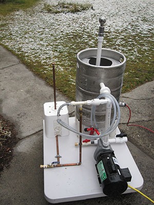
The system I designed accomplishes rinsing, cleaning, and re-rinsing of kegs with minimal changing of hoses. When the cleaning and rinsing cycles are finished, the kegs are ready to be broken down and sanitized.
To achieve this the system uses a re-purposed keg as the cleaning solution vessel (CSV). It is outfitted with a drain in the bottom (I used a stainless steel bar sink drain from the hardware store for a weldless solution), an electric element to keep the solution hot, and a temperature probe for the element’s controller. The heating element shouldn’t be left out of this project as effective CIP cleaning (in a reasonable amount of time) requires a hot cleaning solution. The top of the keg is cut to support the handles of a corny keg, with notches for clearance of the port cleaning hoses.

The pump I used is an AMT 429B-98. This is a 3⁄4 horsepower pump with a stainless head. Its seals are chemical resistant and it is rated for fluids up to 200 °F (93 °C). These pumps are usually cost-prohibitive for homebrewers, but I found a new one on eBay for under $200. You don’t have to buy this exact pump to build a great CIP system, but I would recommend something with at least 1⁄2 HP and the above-mentioned properties for safe, effective cleaning.
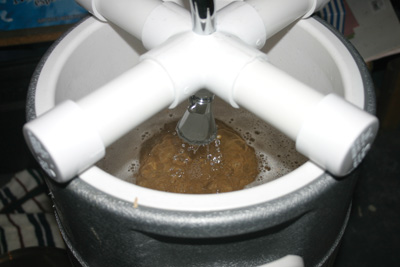
Cleaning solution is pumped from the CSV and up through a stainless spray ball that sits inside the inverted corny keg. The solution drains out of the keg and back into the cleaning solution vessel. There is a 1⁄2 in. (13 mm) port on the 90° elbow above the pump that allows the cleaner to flow through a check valve and into the two hoses that connect to the liquid and gas ports of the corny keg.
When washing is complete, the port cleaning hoses stay connected to the ports. The corny keg is removed from atop the cleaning vessel and placed on the rinsing wand. The rinsing wand (a vertical copper pipe drilled with a series of 1⁄8-inch/3-mm holes) and its plumbing are all made of potable water rated components (CPVC and copper). When the rinse water valve is opened, cold tap water flows to the rinsing wand and through a tee and a check valve to the port cleaning hoses. The check valve on the cleaning side prevents rinse water from entering the cleaning loop, just as the check valve on the rinse side prevents cleaning solution from entering the rinse apparatus. Once the keg has been sufficiently rinsed, it is ready to be broken down and sanitized.
To put the unit into storage I disconnect power from the pump and heating element and open the dump valve (see photo). When the cleaning solution has emptied I close the dump valve and then hook a fresh tap water hose to the feed side of the pump and close the valve below the vessel. This forces the rinse water up through the pump and the spray ball. It’s handy to have a spare corny keg sitting on the unit for this so you don’t get soaked! Finally, I re-open the dump valve and open the valve directly below the CSV and give it a good hand rinsing.
Since your pump may vary from mine, the materials list is approximate. Pick out the fittings that suit your needs to accomplish the same functions as my machine.
BUILD YOUR OWN CIP SYSTEM
This is an advanced project that should only be attempted by those familiar with plumbing and wiring. If any parts of this project are assembled improperly you risk failure of key components, injury, electrocution, and making a gigantic mess.
Materials:
* A base for the project, preferably with wheels. I used a plastic table top screwed to a plastic furniture dolly.
* 10 ft. (3 m) length of 1 in. (26 mm) schedule 40 PVC pipe (or appropriate diameter for your chosen pump)
* PVC cement
* (2) 1 in. (26 mm) PVC valves (I like to use a “socket” style valve for easy disassembly)
* Stainless bar sink drain kit and reducers to attach the 1.5-in (38-mm) drain pipe to 1 in. (26 mm) PVC.
* 1 in. (26 mm) schedule 40 PVC cross
* 2 garden hose adapters
* 1 in. (26 mm) PVC elbows (quantity and types depend on your final design)
* 1 in. (26 mm) PVC elbow with 1⁄2 in. (13 mm) FPT port
* 1 in. (26 mm) PVC socket union fitting
* Brewer’s Hardware Rotating CIP Spray Ball (1 in./26 mm)
* PVC spring check valve for cleaning look
* Lead-free brass check valve for rinsing loop
* 1⁄2 in. (13 mm) CPVC tee for rinsing loop
* 1⁄4 in. (6.4 mm) barb tee for port cleaning hoses
* 8 ft. (2.4 m) clear 1⁄4 in. (6.4 mm) PVC beer line for port cleaning hoses
* Gas in and beer out fittings for corny kegs
* 6 ft. (1.8 m) of 1⁄2 in. (13 mm) copper pipe
* All of the needed copper tees and elbows for your rinsing setup
* 1⁄2 in. (13 mm) copper cap
* Lead-free solder
* Water-soluble flux
* Teflon tape
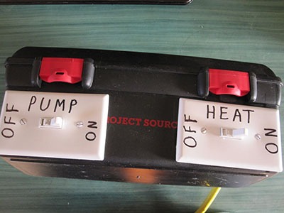
* Pump rated for high temperature chemical handling, I used a 3⁄4 HP with 1 in. (26 mm) inlet and outlet and a maximum 75 psi working pressure * A switchbox for the pump and heating element
* Weldless temperature probe
* 2500W, 240V heating element (I run it on 120V, so it only consumes 625W of power) with stainless nut
* Heavy gauge wiring for the pump and element (at least 12 AWG)
* GFCI plug for the switch box
* 2 in. (53 mm) PVC Pipe to make supports for cleaning solution vessel
Tools Required:
* Electric drill
* Step-drill bit with max step at least 13⁄8 in. (35 mm)
* Jigsaw with high-quality metal-cutting blades
* Chopsaw for cutting PVC (not necessary, but it provides nice square cuts)
* Copper tubing cutter
* Soldering torch
* Pipe wire brushes
* Pipe wrenches
* Level
* Framing square
* Gloves
* Safety glasses
* Ear Protection
Step by Step

STEP 1: BUILD THE BASE
This project is heavy and requires a solid corrosion-resistant base. Since I didn’t find a great stainless cart at the scrap yard, I chose to use half of a 3 ft. x 6 ft. (0.9 m x 1.8 m) folding table.
I then screwed the table top to a cheap 1,000 lbs. (450 kg) plastic furniture dolly from Harbor Freight.
Please make sure you acquire your keg legally. Just because you paid for a keg on Craigslist or forfeited your deposit to a retailer, does not mean the keg was legally acquired from the brewery.
While the author used a jigsaw to cut his keg, angle grinders and plasma cutters are also effective tools for cutting the tops off of stainless steel kegs.

STEP 2: CLEANING SOLUTION VESSEL (CSV)
Procure a keg legally. Relieve the pressure on the keg. Cut the top as shown with the jigsaw to allow the handles of a corny keg to sit on the remaining stainless steel, with two slots cut out to allow clearance for the port-cleaning hoses. You can use an empty corny keg to trace the pattern. Drill holes in the side of the keg with the step-drill bit to allow for the heating element and temperature probe, making sure the two items will clear each other when installed. Finally, turn the keg over and cut the bottom to accept the bar sink drain. This is a bigger hole than a step drill bit, so I used my jigsaw to carefully cut the circle. An appropriately sized hole-saw or knockout punch would also work. Flatten the rim of this cut if the keg bottom has been dented from its service life. This will ensure a good seal for the drain. Use a file to de-burr and round over all holes and cuts. Install the components according to the manufacturer’s directions and check for leaks by filling the vessel with water.

STEP 3: PLUMBING THE CLEANING LOOP
Even though you have these directions in front of you, take the time to draw out your cleaning loop and rinsing apparatus and label the individual plumbing fittings. This will serve as your parts list when you go to the store. You will inevitably have to visit a few different hardware stores or order parts online to get everything you need. Be sure to buy spring-actuated check valves. The “swing” check valves don’t provide as positive of a seal. Also, be sure that the valves are properly temperature-rated for the type of temperatures required.
With materials in hand, you can now begin assembly. Support the cleaning solution vessel using the 2-in. (53-mm) PVC pipe. Begin by cutting the PVC into four equal length sections. Notch these pipe segments equally to fit around the bottom keg chime.
Assemble the plumbing to convert from the bar sink drain to 1-in. (26-mm) PVC. From there you will go 90° from vertical to horizontal and install your first valve. I used a “socket” type valve here so I could separate the plumbing if I ever needed to do repairs. The purpose of this valve is to force rinse water up through the pump and the spray ball when the day is done. Next you will add a cross. One side of the cross will get necked down to 1⁄2 in.
(13 mm) pipe and a garden hose adapter for rinse water. The other side will have a valve for dumping cleaning solution. The opposite side of the cross feeds the pump.
From the pump discharge, plumb up vertically to a 90° elbow fitted with a 1⁄2-in. (13-mm) threaded take-off port (more on this later). From there, run a horizontal section of pipe back through the wall of the cleaning solution vessel (make sure it is drilled so the pipe fits snugly). I used a socket-type union here as well to allow for disassembly. Then attach another 90° elbow inside the cleaning solution vessel to accept the vertical pipe with the spray ball. I calculated the length of this pipe so that the top of the spray ball protrudes about 15 in. (38 cm) from where the corny keg seats on the cleaning solution vessel.

STEP 4: PLUMB THE CLEANING-RINSE LOOP INTERCHANGE AND PORT CLEANING LINES
From the 90° elbow with the 1⁄2 in. (13 mm) threaded port, plumb the PVC spring check valve with the arrow pointing away from the cleaning loop. On the other side of the check valve, plumb a CPVC or other potable-grade material tee to accept the lead-free brass spring check valve from below. The arrow on this valve should be pointing up, allowing the rinse water to flow to the port-cleaning hoses. The port cleaning hoses (PVC beer line) are attached to the other side of this tee. I used a 1⁄2-in. (13-mm) MPT x 1⁄4-in. (6.4-mm) nipple fitting to convert to soft beer line, and then put a 1⁄4-in. (6.4-mm) barb tee in after this to split off for the gas and liquid fittings. Clear draft line is ideal as you can see the change happening between cleaning solution and rinse water, verifying flow to the gas/beer ports.

STEP 5: BUILD THE RINSE WAND
Cut a length of 1⁄2-in. (13-mm) copper to 26 in. (66 cm) and solder a cap on one end. Drill three 1⁄8 in. (3 mm) holes in the edge of the cap, plus one in the center. Then drill a few holes around the pipe until 16 in.
(41 cm) down from the cap (you can get creative with your hole pattern, just don’t drill so many holes that you lose water pressure at the cap). Cut off the bottom of a bucket at 10 in. (25 cm) to support the keg for rinsing. Drill holes as needed to allow clearance for the rinse plumbing. You could also use a milk crate or something more elegant.

 STEP 6: PLUMB THE RINSE SIDE
 With your cleaning loop in place, the rinsing loop can be measured and assembled. The exact measurements will depend on the base size, type of pump, and geometry of your loop. I used all potable water-grade components on the rinse side.
Be sure the female hose thread adapter is either elevated or protruding slightly from the edge of your base so threading the RV hose on and off is easy. Then mark the base where you want the rinse wand to rise vertically. Now use a level to mark the base where the copper will rise to the port rinsing check valve. Use these points to measure the lengths of copper you will need to plumb it. Don’t forget that 1⁄2 in. (13 mm) copper slip fittings take up 1⁄2 in. (13 mm) length of pipe at each connection.
Using these measurements, solder the rinsing apparatus together on a heat-resistant surface. Use a level to ensure the two vertical pieces will be plumb once erected on the base. Solder a 1⁄2-in. (13-mm) MPT adapter on the input side of the tee.
Connect the riser to the check valve and fit the ball valve and hose adapter to the pipe thread adapter. Secure the unit to the base using poly plumbing strap and coated screws.
STEP 7: GIVE IT POWER!
Wire the pump motor according to the manufacturer’s instructions. Use at least a 12 AWG cord to avoid voltage drops. Wire the heating element, being sure to adequately protect the electrical connections. Build a switchbox with two switches, one for the pump and the other for the element. You can incorporate a temperature controller and relay for the heating element into the box if desired. The power feed for the switchbox should use a GFCI plug to protect you and your equipment. Fill the cleaning solution vessel with water and connect a hose to the rinsing side. Pour yourself a well-earned homebrew and see how it works!
TIP: While this system does not incorporate a temperature controller, you could easily add one (such as a PID controller or a Ranco) to the control box to turn the heating element on and off. But the system loses so much heat when the pump is running, that the element stays on constantly to maintain temperatures.