Motorize Your Grain Mill
DISCLAIMER: WE ARE WORKING WITH 115V. IF YOU ARE NOT COMFORTABLE WITH YOUR ABILITIES, CONSULT AN ELECTRICIAN OR SOMEONE WHO IS.
Like many, I started out with extract, moved to extract with specialty grains, partial mash, then all-grain. Up until I reached partial mash, I used zip-top bags and a rubber mallet to crush my grain. When I reached partial mash, I found I could not continue my process and had the local homebrew shop crush my grain. Worried about my crushed grain going stale and consistency of the crush, I wanted my own mill.
I purchased a Monster Mill 2 and began making plans, scrapped plans, and made new ones. Rinse and repeat. Five years later, I finally finished and ran grain through it for the first time.
Monster Brewing Hardware, makers of the Monster Mill, suggest running the mill at approximately 150 rpm. I initially looked to follow suit of many brewers with a standard farm duty (or similar) 1725 rpm motor (available at many retailers) to drive the mill using a belt and sheaves. This would require a small sheave (driven pulley) on the motor with a large sheave (12+ inches/30+ cm diameter) on the grain mill. I did not like the idea of such large sheaves. Others also use low-speed drills to drive the mill, but these are a pain not only to mount, but also to maintain the proper speed. I also looked at a gear system, but I could not locate an inexpensive set for low horsepower motors. It then occurred to me that there is a piece of equipment that many of us use every day, is inexpensive, and has a gear system built in — a garage door opener.

Chain drive garage door openers are typically in the 1⁄2 to 1 horsepower range. They operate with a worm gear on the motor shaft, which turns a gear on a secondary shaft attached to the chain sprocket. This would be perfect. To the best of my knowledge, belt drives also operate the same way. Screw-drive openers, however, will not work.
A major obstacle was how to attach the mill to the opener. Because the opener and the mill had two different shaft diameters, I chose to use a Lovejoy connection. They are removable, allow for some slight misalignment, and can absorb a small amount of torque in case a rock or something makes its way to the rollers.
Another obstacle is to rewire the opener to run continuously instead of the short distance to lift or close the garage door. I removed the circuit board and wired the motor directly to relays (details in the step by step).
The last major obstacle is heat. Garage door openers are only designed to move the door a few times an hour. To crush 12 lbs. (5.4 kg) of grain, it needs to run continuously for upwards of five minutes. I chose to place a fan in the bottom of the opener to blow air up through the motor.
As of today, I have crushed around 36 lbs. of grain without any issues. As the gears are plastic, I will keep an eye on how they wear. If (or when) they get bad enough, replacements are available for under $20.
PARTS & TOOLS
Garage door opener (chain drive)
Monster Mill and hopper
Lovejoy 10208 L050, .375” bore (mill side)
Lovejoy 10210 L050, .5” bore (motor side)
Lovejoy 37786 L050 coupling spider
5VDC cell phone charger
2-channel relay board (Dx.com, Item 144140)
2 switches, SPDT
Project box
Wire
Replacement extension cord plug
115VAC 120mm muffin fan
Dust covers for fan
3⁄4-inch plywood or orientation
strand board (OSB)
2×1 and 2×2 boards
Screws
5-gallon (19-L) bucket
Step by Step
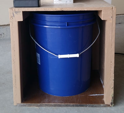
1. BUILD A BOX
I chose to use a 5-gallon (19-L) bucket to catch my grain. With the mill mounted on the top of the box, I only needed to make the box slightly taller than the bucket to clear the mill’s mounting bolts. Limiting the distance between the mill and the top of the bucket should also cut down on the dust. I constructed the box using 2×2 and 2×1 boards for a frame and Orientation Strand Board (OSB) for the outside. I painted the box with some paint we had around the house to make dust cleanup easier.
While not necessary, casters or wheels would also make it easier to move the mill around your brewery. Now would be a good time to install these.

2. MODIFY THE OPENER
First, the main circuit board needed to be removed. The board was mounted vertically at the top of the picture. A smaller circuit board with the limit switches must also be removed along with the small gear attached to the drive shaft. This was mounted where the grey/yellow/purple wires end (indicated by A in picture).
The limit switches, the RPM sensor (on the end of the motor shaft), incoming power, and the motor were all connected to the main Printed Circuit Board (PCB) with a single connector. The connector was cut off and only the necessary wires kept.
While not necessary, I kept the RPM Sensor since it is not in the way. In the future, I might add my own RPM display to the mill. (These are the unconnected grey, purple, and yellow wires also found at A.)

3. WIRE THE MOTOR
I wanted to keep all the high voltage inside the motor’s enclosure, so I chose to use relays to operate the motor instead of switches. I used relay board that worked off 5VDC. The opener had a terminal block where power came into the unit, so I wired an extension cord end to the block (indicated by B in picture) and plugged in a cell phone charger (indicated by C in picture) to supply 5VDC to operate the relays.
I wanted the ability to reverse the motor in case the mill jammed. This requires two relays – On/Off and Forward/Reverse. Power from the terminal block goes in the first relay (On/Off). When on, the power then flows through the second relay to one of two motor windings, Forward or Reverse.
The relay board (indicated by D in picture) is mounted in an open area in the top of the opener. For safety reasons due to the relays having bare connections on the back, I placed a piece of plastic between the relay board and the metal frame. The plastic is screwed to the metal, and the board screwed to the plastic, such that the board’s screws do not fully penetrate through the plastic, providing isolation.
I mounted the switches in a project enclosure on the front of the mill. The switches were wired using the leftover safety sensor wire and secured at any point the wire touches metal so any vibration cannot chafe the wire.

4. MOUNT MOTOR AND MILL
The flanges for the garage door opener were about 1 1⁄4 inches deep, so I chose to mount the opener on 2×2 (actually measure 1.5 inches square). This allowed me to move the opener up and down to maintain alignment with the mill. After the opener was in position, I located the mill and cut the hole for the crushed grain to drop down into the awaiting bucket.

5. MATE THE MILL WITH THE OPENER, ADD HOPPER
I chose to use Lovejoy couplers to mate the mill to the opener. They are small in size, come in multiple shaft sizes, and can handle a small amount of mis-alignment. I had to grind down a flat spot on both shafts to have a place for the set screw to sit.
Once the mill is connected, bolt the mill in place. Make sure all fasteners are in place, and add your hopper to the top of the mill.

6. INSTALL AND WIRE THE FAN
In order to remove heat from the motor, I purchased a 115VAC 120 mm Muffin Fan (commonly used for cooling computers), cut a hole in the top and bottom plastic panels, and mounted the fan to the bottom to blow air up and across the motor. I chose to blow up because heat rises and dust falls. I added dust filters to both the top and bottom to keep as much grain dust out as possible.
The fan is wired to the incoming power terminal block and is always running if the unit is plugged in.