Keg management is an important tool in any kegging brewer’s arsenal. Being able to keep track of keg levels is vital to brew scheduling and not being surprised at your summer BBQ when the keg kicks unexpectedly. Until recently, I’ve been using the method of when you pull the tap handle and beer comes out, that means there’s still beer in the keg. When no beer comes out, the keg is empty.
There is a small variety of DIY and commercially available systems out there. In-line flow meters, the ol’ ball and magnet thing, pull the keg out to room temperature and let it sit for a few minutes until it sweats at the level line. The one I liked the most is the Plaato system that came out not too long ago. I really like the idea of the Plaato system because it uses a scale to very closely approximate the remaining beer in the keg. I just couldn’t pull the trigger on the $130 per scale price tag, and I need three, so I found that be a little cost prohibitive. After some more research, I ran across a YouTube video of a guy who made a scale out of a piece of plywood and some electronics on the cheap. Not just a little cheap. I mean cheap, cheap. I was intrigued . . .
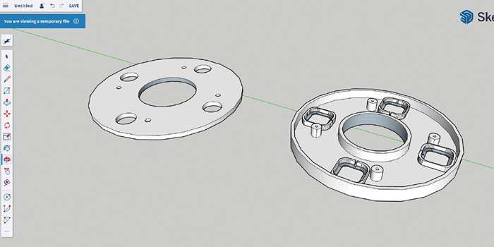
Some more internet research and I found someone else who used the same materials, but upped the game by 3-D printing a housing and added LEDs to it. My only problem with his design is that the diameter was wider than a corny keg and definitely too wide for my 3-D printer. I have a standard-sized kegerator and the kegs fit in there snugly as it is. So, it was high time to design my own. I used Google SketchUp to bring this to life.
I was able to design a scale that was the exact diameter of a corny keg and only lifted it about an inch (2.5 cm) off the bottom of the kegerator.
I was able to design a scale that was the exact diameter of a corny keg and only lifted it about an inch (2.5 cm)off the bottom of the kegerator. It’s a little tighter up top, but not impossible to connect gas and liquid lines.
After the design was finalized and the proof of concept was there, I decided to go for it. The price point was right for me too. At less than $10 per scale for the boards, Home Assistant being free and open sourced, add-ons not costing a cent, plus I had some USB cables in the infamous box of extra cables . . . it was worth a shot to see if I could do it.
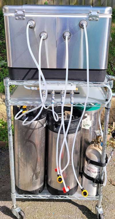
This scale can be used in kegerators, keezers, fridges, and it doesn’t have to stop at kegs. You can even use it to monitor CO2 tank levels or anything up to 110 lbs. (50 kg) that will fit on the scale.
This project is going to be relatively easy if you have experience with Home Assistant, are an avid tinkerer, or are just a good old-fashioned tech nerd like me.
3-D printer (with minimum 235 mm x 235 mm build plate)
Printer filament (172 meters / 511 g per scale)
(4) M4 x 0.7 x 12 mm screws
M4 x 0.7 tap
HX711 load cell amplifier (with four load cells)
ESP8266 (USB-C)
USB to USB-C cable
USB power brick
Soldering iron
A computer running Home Assistant
Steps
1. Print Scale Housing
I took certain design aspects of those that I saw online and modeled one to suit my needs. Along with the housing, I also made feet and retaining clips to keep the load cells in place. The only glue that is needed is when assembling the feet through the bottom plate and securing the circuit boards. The load cells are kept in place with friction and some clips for extra insurance.
After I had a prototype I was happy with (Figure below), I printed the first production scale using PLA with 70% infill.
2. Boards and Wiring
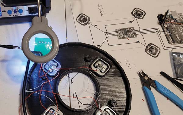
Wiring is pretty straightforward and there are tons of diagrams, forums, and pages on how to wire the boards around the internet. An important thing to note is that some of the wires on the boards can be wired to different D pins, but if you are doing more than one scale, it’s important to wire them all the same for continuity.
These boards are small — a magnifying glass and a steady hand are key here. Cut to size, strip, then solder the wires to the board per the diagram on the right (Figure below) and solder the black and white load cell wires to each other per the Wheatstone circuit (Image below). The solder doesn’t have to be pretty. It just needs to keep the wires in place and make sure you don’t have the solder pools touch one another. Electrical tape or heat shrink tubing will keep the connections safe and secure.
Tip: I used my prototype 3-D print to hold the load cells and boards while the production print was going.
3. Assembly
After all the pieces are printed and the soldering done, it’s time to do some assembly. Start by tapping the screw bosses with the M4 x 0.7 tap. Putting a piece of tape on the tap threads can act like a depth-stop so you don’t go too far.
Next, glue the feet together through the bottom of the scale. The smaller part of the foot should be on the inside and the larger foot should be on the outside. The outside has the countersinks for the screws.
Then place your load cells in their respective housings following the same Wheatstone bridge that you assembled them in followed by the retainer rings – these are just friction fit. Use some tape or hot glue to manage the wires and fix the circuit boards in place.
Lastly, you will need a hole or slot for your USB cable (Image below). A drill or Dremel will make quick work of this part. Finish it with a file and/or blade to refine the fit, if needed. Affix the top and bottom with the four screws and you have a fully assembled scale!
4. Home Assistant
I am using Home Assistant with the ESPHome add-on to do all the configuring for my load cells. I had an old Intel NUC lying around so I figured I can run Home Assistant on that. You can choose to run it on a stand-alone computer, as a virtual machine, or on a purpose-built Raspberry Pi. Whichever one you choose depends on your setup and needs. Please see the Home Assistant webpage for more details.
5. ESPHome
Once Home Assistant is installed, install ESPHome from Settings→Add-ons to add your scale to Home Assistant. Plug the scale into the computer running Home Assistant. In ESPHome, choose to install a new device. Follow the prompts to complete the installation.
After the installation completes, click on “Edit” in the scale’s window. Here you will see some default code in yaml. You don’t need to edit this, but you will need to add some of the code to get everything displaying correctly. You can copy the code (Figure below) to set up your sensor at the bottom of the existing code, starting around line 29. Please note the “calibrate linear” data will differ with your keg depending on the tare and full weight. You may also change the “update interval” depending on how often you want the values to update. I find 60 seconds to be good. Enter this code under “captive_portal:” then click “save”, and then “install”. You may have to restart Home Assistant a time or two during the process for the scale to fully install.
Note: If any of your values are negative numbers, it’s likely that you have mis-wired the red wires on the load cells. Go back and double-check the Wheatstone bridge.
Photos by Myke Martin
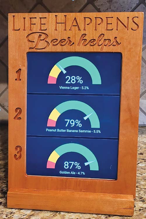
6. Display
Displaying your keg level is done with “cards” within Home Assistant. Cards are what make up the dashboard. There are many card options. I chose the gauge in a three-card vertical set. Although there are many ways to display the keg scales from Home Assistant using any network-connected device, I wanted a classy screen on a stand display near my kegerator. You can choose any display method you prefer. Here is how I chose to do mine: I got an old iPad and installed a kiosk app on it. I set the iPad to never turn off, but set the kiosk app to black the screen after X minutes of inactivity. These settings allow me to just tap the screen when in idle state to see the keg levels.
For my frame, I milled up some scrap cherry to hold the iPad. I used a small CNC router to carve text into the wood to show the tap number and added a little quip at the top. My little CNC router travel is a bit too short to do the whole thing, so I had to break the lettering into segments and route out the opening for the iPad by hand.
In my case, because of the layout and formatting, I had to install the iPad upside down. I wanted to limit the times I would have to remove the iPad, so I drilled a small hole in the ‘r’ so I can easily press the ‘home’ button with a finish nail whenever needed.
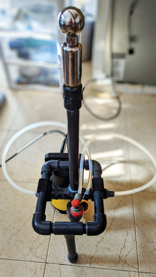
For those that use a jockey box, most know maintenance can be a pain. A homebrewer decided an upgrade was needed on his with the goal of eas
This website uses cookies to improve your experience. You can opt-out if you wish.AcceptRejectRead More
Privacy & Cookies Policy
Privacy Overview
This website uses cookies to improve your experience while you navigate through the website. Out of these, the cookies that are categorized as necessary are stored on your browser as they are essential for the working of basic functionalities of the website. We also use third-party cookies that help us analyze and understand how you use this website. These cookies will be stored in your browser only with your consent. You also have the option to opt-out of these cookies. But opting out of some of these cookies may affect your browsing experience.
Necessary cookies are absolutely essential for the website to function properly. This category only includes cookies that ensures basic functionalities and security features of the website. These cookies do not store any personal information.
Any cookies that may not be particularly necessary for the website to function and is used specifically to collect user personal data via analytics, ads, other embedded contents are termed as non-necessary cookies. It is mandatory to procure user consent prior to running these cookies on your website.