About two years ago, I decided it’s time to get back into homebrewing. Let’s clarify that one of the primary motivators for me to stop brewing about 10 years ago was all the time that I had to set aside for washing and sanitizing bottles. This time was going to be different. After convincing my wife to move the kitchen table outside to make room for a kegerator, I knew I had the green light.
All photos by Derrick Marlow
Kegging batches was going great, but I was really starting to get tired of that soul-crushing feeling of a keg blowing when I had no idea I had already drank that much. In line with most of my other first-world problems, I decided to do absolutely nothing about it. Fast forward to March 2020: Pandemic, quarantine . . . golf courses are closed, so can’t go out and shoot double bogey on every hole. Breweries are closed, so I can’t sit around and complain about my golf game to strangers. And finally I’m stuck inside forced to drink whatever hooch I brew in my backyard.
With all the extra time on my hands, I decided that I would pick up a new hobby . . . electronics. With a background in industrial automation in the water industry, I knew there had to be another way to monitor the keg level than using flow sensors or scales. Not that I’m opposed to those measurement methodologies, I just thought to myself, “Why can’t I just have a sensor as part of the keg lid”?
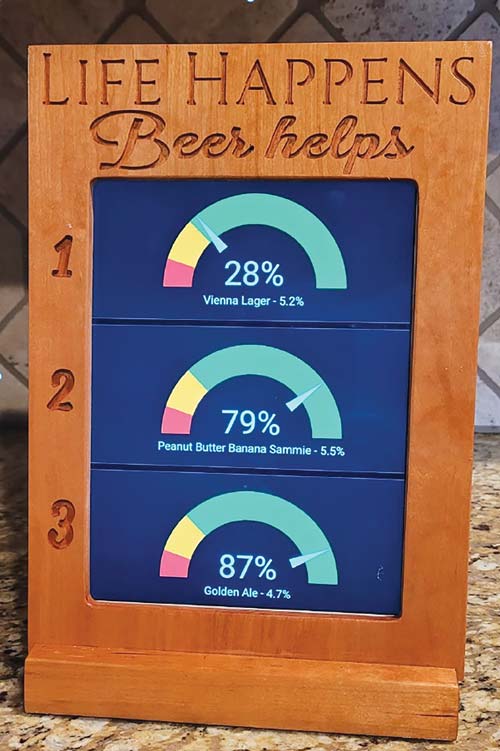
It’s great to have an idea of how much is left in the keg to plan future brew days and schedule the current brew fermenting.
I decided to pull the trigger on a time-of-flight sensor to measure the distance from the lid to the surface of the beer. I knew that this distance could be easily converted to a unit of volume. While I was at it, I realized that if this sensor is going to be part of the lid, why not monitor temperature and CO2 pressure while I’m at it? At that point, I knew I had to build a sensor that could measure everything from inside of the keg. Sacrificing an old Corny keg lid and designing a 3-D printed enclosure, I built an integrated keg lid level, temperature, and pressure sensor. For about $65 (USD), you can build one of these for yourself!
This sensor has been useful and a lot of fun. It’s great to have an idea of how much is left in the keg to plan future brew days and schedule the current brew fermenting. I also decided to take it a step further and develop a mobile app. Using the mobile app, if the in-laws come by to watch the cat while my wife and I are out of town, I’ll know if they didn’t try any homebrew . . . which is basically a requirement when they come over. This could come in handy for homebrewers who are parents of teenagers as well.
Moving forward, and with awesome support from the homebrewing community, I have been developing this model for support with Android and iOS, open-source hardware like Arduino and Raspberry Pi, and other brewing community platforms.
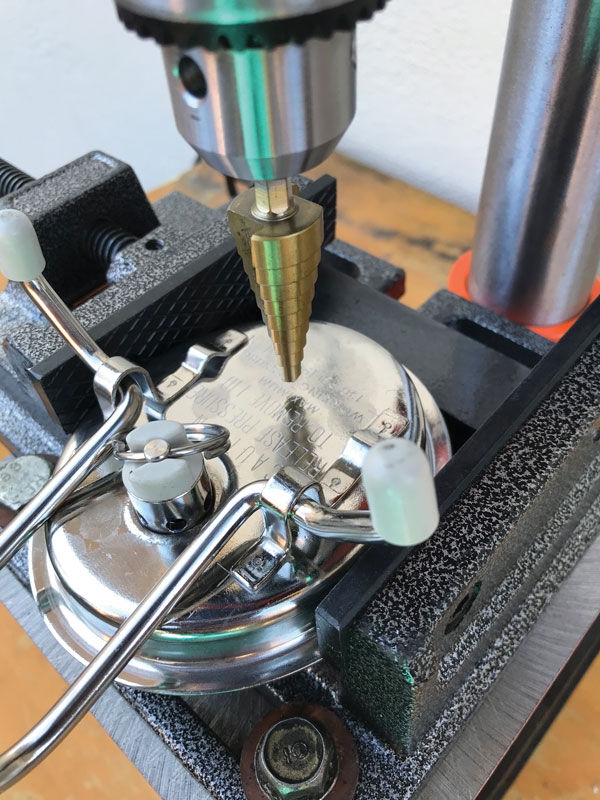
Drill a 5⁄8-in. (16-mm) hole in the Corny keg using a drill bit for stainless steel. Make sure to follow best drilling practices with RPM, lubrication, and bit type. This hole should be centered between the lid handle mounting brackets and approximately halfway between the PRV (pressure release valve) and the lip of the lid (above). Install the male 4-pin GX16 aviation connector to the keg lid with the connector facing towards the outside of the keg. Install through the lid AND the cover of the 3-D printed sensor enclosure (below).
2. Solder Sensors
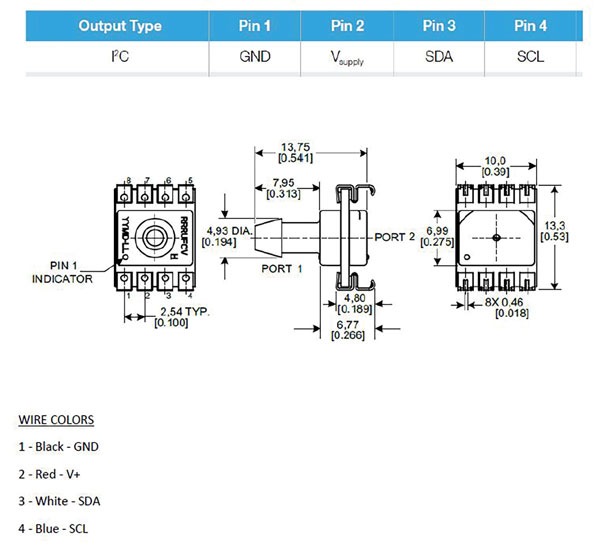
Solder wires (preferably different colors for each pin) to the legs of the pressure/temperature sensor based on pinout drawing (above). Through-hole solder wires to the VL53L0X breakout board. Match the same wire colors as noted in the picture (2A). Fortunately, the breakout board’s wiring schematic should be labeled for you. Make sure the wire is coming into the breakout board on the OPPOSITE side of the sensor itself. Trim any additional exposed wire, it should not extrude past the cavity in the bottom of the sensor enclosure. When finished, the sensors with wires should look like the picture (below).
3. Solder Connector
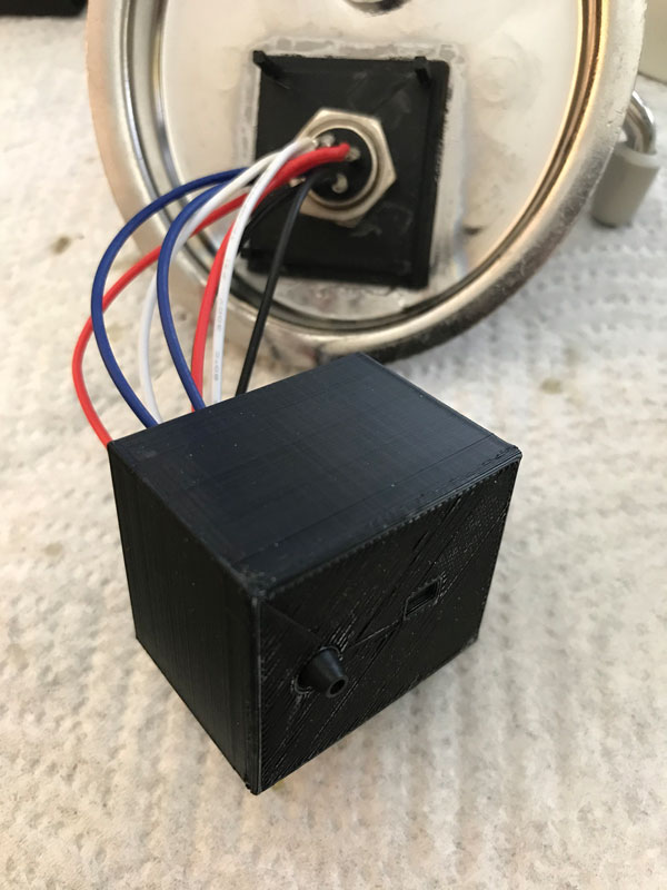
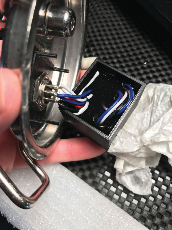
Strip all the wires in step 2 and twist each color’s stranded wire with the other sensor’s wire of that color. Solder each twisted set to the single connector terminal based on the pinout (above). Once finished, it should look like the picture (below).
4. Glue Sensors
The sensor enclosure is designed with a cavity designated for the pressure/temperature sensor and a separate cavity for the VL53L0X Time-of-Flight board. If you can’t figure out which one is for which sensor, it’s probably time to set down that beer and call it for the day. You’ll need your wits about you for this next step. This next part is the most critical part of the sensor assembly, so take your time here. You will need to install and glue each of the sensors into their respective cavities. For the VL53L0X, this glue must seal AROUND the face of the sensor where the board meets the enclosure.
5. Epoxy Stage One
Once the glue has dried, coil the wires into the sensor enclosure and do a “test fit” to make sure the enclosure will sit flush with the lid. Mix your food-grade epoxy based on the instructions on the epoxy bottles. Once sufficiently mixed, pour the epoxy into the sensor enclosure, making sure to hold the enclosure upright and level while pouring. Pour until the level is high enough for the “legs” of the enclosure lid to make contact with the epoxy when the lid is flush with the enclosure (above).
Holding the enclosure (full of liquid epoxy) level, place the lid into the enclosure until the lid is flush with the enclosure body. Place the lids SENSOR SIDE DOWN on the edge of a surface allowing the nipple to extrude over the edge (below). Add weight above the connector to keep the lid from tipping over. I’ve found sockets are a nice tool for this.
For the pressure/temperature sensor, the glue must seal where the base of the sensor nipple meets the enclosure. I recommend Loctite with the SF 7452 accelerator. Applying the bead of Loctite on the enclosure, then spraying the sensor’s mating surface with the accelerator creates a fast-acting (10–15 seconds) seal. This seal is critical prior to potting the sensors in epoxy. Don’t be afraid to be liberal with the glue where the sensors meet the enclosure. Don’t ask me how I know, but if they aren’t sealed, epoxy will leak everywhere in step 5. Just be sure to test the seals after the sensors are glued to ensure they are waterproof.
6. Epoxy Stage Two
After the stage 1 epoxy has fully cured (follow directions of epoxy bottles), place the lid SENSOR SIDE UP on a level surface. You may need to use something under the lid handle to make sure the underside of the lid is level. Apply a bead of glue along the outside of the sensor enclosure where it meets the lid. As mentioned in step 4, this must be sealed, or epoxy may leak in this step. Once the glue has dried, mix your epoxy based on the instructions on the epoxy bottles. Once sufficiently mixed, pour the epoxy into the underside of the sensor lid. Pour slowly and allow the epoxy to fill evenly around the sensor enclosure and PRV. Fill until the mating surface of the sensor enclosure and lid is covered, but DON’T pour past the PRV. Once the epoxy has cured, you have successfully built your own Time-of-Flight keg level sensor! The Flite sensor is designed to work with the Flite display or headless controller and supports integration into other brewing community platforms. For more details check out the support documentation at: https://www.flitesense.com/support
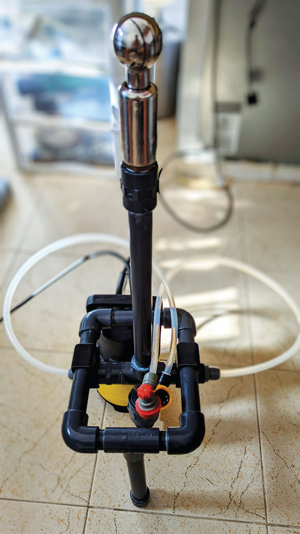
For those that use a jockey box, most know maintenance can be a pain. A homebrewer decided an upgrade was needed on his with the goal of eas
This website uses cookies to improve your experience. You can opt-out if you wish.AcceptRejectRead More
Privacy & Cookies Policy
Privacy Overview
This website uses cookies to improve your experience while you navigate through the website. Out of these, the cookies that are categorized as necessary are stored on your browser as they are essential for the working of basic functionalities of the website. We also use third-party cookies that help us analyze and understand how you use this website. These cookies will be stored in your browser only with your consent. You also have the option to opt-out of these cookies. But opting out of some of these cookies may affect your browsing experience.
Necessary cookies are absolutely essential for the website to function properly. This category only includes cookies that ensures basic functionalities and security features of the website. These cookies do not store any personal information.
Any cookies that may not be particularly necessary for the website to function and is used specifically to collect user personal data via analytics, ads, other embedded contents are termed as non-necessary cookies. It is mandatory to procure user consent prior to running these cookies on your website.